Land application is the most desirable method for making use of the nutrients and organic matter in animal manure. The value of the manure is usually maximized if it can be substituted for the purchase of commercial fertilizer.
Under the U.S. Environmental Protection Agency's Unified National Strategy for Animal Feeding Operations, the desired outcome is for all concentrated animal feeding operations to develop and implement a comprehensive nutrient management plan. This plan should address, as necessary, feed management, manure handling and storage, a nutrient management plan for land application of manure, land management, record keeping, and options for making use of manure. In addition to nutrients, the plan should address other pollutants, such as pathogens, to minimize the effects of animal feeding operations on water quality and public health.
At a minimum, nutrient management should prevent the application of nutrients at rates that exceed the capacity of the soil and the anticipated needs of crops. To determine nutrient needs and content, soils and manure should be tested and nutrient removal by crop yield should be evaluated. Manure application equipment should be calibrated to ensure that the intended quantity of material is being applied. Records of crops removed annually and the total amount of manure applied should be kept to maintain the desired nutrient balance. Electronic totalizing flow-rate meters in slurry and lagoon pumping systems are frequently used by custom applicators to calibrate equipment and record the amount applied per acre. These meters can also be a component in site-specific variable-rate application. GPS guidance systems can facilitate record keeping and help in maintaining correct "swath width" for broadcast applicators, including maintaining proper separation distances from wells, streams, water impoundments, sinkholes and property lines.
Environmental comparisons
Table 1 compares various manure application systems by means of an environmental rating system developed at the University of Nebraska and based on five important factors. The first of these is that manure application equipment should provide uniform application, similar to that of fertilizer or chemical applicators, and should be easily calibrated for the desired rate per acre. Timeliness of manure application is an important consideration because there is usually a short window of time when field conditions are suitable and losses will be minimized. Conservation of ammonium nitrogen varies with the method of storage and with weather conditions after manure is applied and before it is incorporated into the soil and used by the crop. Manure application systems vary widely in the resulting odor emissions (nuisances) after application. This is often the determining factor in the choice of application method, especially in densely populated locations.
The high volumes and weights of manure normally handled, usually during the spring and fall when the soil is wet and subject to compaction, give an advantage to systems that pump the manure to the field. In general, systems treat manure as a solid or semisolid to be hauled and spread, or as a liquid (such as a slurry or lagoon effluent) that can be pumped and injected by a tractor-drawn applicator or surface applied by irrigation.
Surface application of liquid manure without immediate incorporation can result in significant losses of the available nitrogen due to ammonia volatilization. Ammonia nitrogen losses vary with application method and with soil and climate conditions from near zero to as much as 80 percent due to ammonia volatilization, depending on the time between land application and incorporation of the manure (Table 2). Without incorporation, most volatilization losses occur within the first 24 hours after land application. The Missouri Department of Natural Resources requires use of an ammonia loss factor of 40 percent on permitted facilities using the plant available nitrogen (PAN) procedure.
Slurries are much more odorous than lagoon effluent or dry solid manure. Aerosol sprays produced by mixing manure and air can carry odors for considerable distances as evidenced from the data in Table 3.
Table 1
Environmental comparison of manure application systems.
| System | Uniformity of application | Conservation of ammonia | Odor | Compaction | Timeliness of application |
|---|---|---|---|---|---|
| Solid systems | |||||
| Box spreader: tractor pulled | Fair | Very poor | Fair | Fair | Poor |
| Box spreader: truck mounted | Fair | Very poor | Fair | Fair | Fair |
| Flail spreader | Fair | Very poor | Fair | Fair | Poor |
| Dump truck | Very poor | Very poor | Fair | Poor | Fair |
| Liquid systems: surface spread | |||||
| Liquid tanker with splash plate | Poor | Poor | Poor | Poor | Fair |
| Liquid tanker with drop hoses | Fair | Fair | Good | Poor | Fair |
| Big gun irrigation system | Poor | Poor | Very poor | Excellent | Excellent |
| Center-pivot irrigation system | Fair | Poor | Very poor | Excellent | Excellent |
| Liquid systems: incorporation | |||||
| Tanker/knife injectors | Good | Excellent | Excellent | Poor | Fair |
| Tanker/shallow incorporation | Good | Excellent | Excellent | Poor | Fair |
| Drag-hose/shallow incorporation | Good | Excellent | Excellent | Good | Good |
Table 2
Nitrogen losses during land application. Percent of total nitrogen lost within 4 days of application.
| Application method | Type of waste | Nitrogen lost |
|---|---|---|
| Broadcast | Solid | 15 to 30 percent |
| Liquid | 10 to 25 percent | |
| Broadcast with immediate incorporation | Solid | 1 to 5 percent |
| Liquid | 1 to 5 percent | |
| Knifing | Liquid | 0 to 2 percent |
| Sprinkler irrigation | Liquid | 15 to 75 percent |
Table 3
Odor emission rates during land spreading of pig slurry from manure storage.
| Application method | Total odor emissions* |
|---|---|
| Conventional tanker with splash plate | 1,322 |
| Irrigation | 6,250 |
| Shallow incorporation | 503 |
| Deep injection | 689 |
| Low trajectory spreader with 15 trailing hoses | 130 |
* Odor units per 1,000 gallons of slurry applied, as measured by olfactometer.
The equipment used for land application is usually determined by the solids content of the manure. The consistency of manure is usually classified as solid, semisolid, slurry or liquid, depending on its fluidity. Figure 1 relates the consistency of manure from various species to the solids content. This guide will discuss land application equipment used for each of the four classifications in Figure 1.
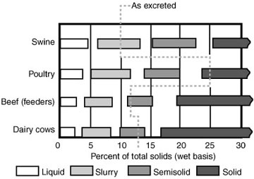 Figure 1
Relative handling characteristics of different types of manure.
Solid and semisolid manure
Solid manure management systems typically handle less weight and volume than liquid systems because evaporation and separation reduce the amount of water in the manure. The volume of manure may be greater if large amounts of bedding have been added to increase the solids content and make the manure less fluid. Solid manure handling equipment may have lower cost and power requirements; however, the labor required for operation and management is generally greater than for other methods.
The most common equipment for applying solids to the land is a rear-discharge, box-type spreader equipped with beaters that broadcast the manure over a width of several feet (Figure 2). Usually, the manure is conveyed to the beaters at the rear by slats attached at each end to a sprocket-driven chain. Some use a powered front endgate to push the material to the beaters at the rear. To handle semisolid manure, a tight-fitting, closable rear endgate is required. Some spreaders have a side discharge; most of these have V-shaped hoppers and feed the material to the discharge with augers (Figure 3). A rotating expeller slings the material out of the discharge port. The application rate is varied by an adjustable gate opening, usually operated by a hydraulic cylinder. Flail-type spreaders have a semicircular hopper bottom and a rotating shaft with chain-suspended hammers to fling the material from the hopper. The flail-type and the side-discharge spreaders are adapted to both semisolid and solid manure.
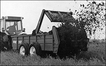 Figure 2
This box-type spreader is equipped with a chain-driven conveyor to move solid manure to the beaters for rear discharge.
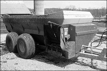 Figure 3
This side-discharge, hopper-type spreader can be used for solid and semisolid manure.
Manure spreaders may be tractor-drawn models or they may be mounted on a truck. Most tractor-drawn spreaders are PTO operated, but some are driven from the ground wheels. Some are hydraulically powered for greater speed variation, especially for the apron drive, to vary the application rate. In the past, spreader capacities varied from about 30 to 400 cubic feet with tractor horsepower requirements ranging from 10 to more than 120.
Note
Some newer spreaders have capacities and power requirements approximately double those figures.
Ratings may be expressed in different ways, from cubic feet struck level to bushels heaped. One bushel equals 1.25 cubic feet.
The distance between successive passes of the spreader must be properly adjusted to achieve the best uniformity of application.
Liquid (slurry) manure
Agitation of the manure storage before and during pumping is recommended to reduce the buildup of solids and for a consistent application of sampled nutrients. In the past, most slurry has been transported to the field in tank wagons equipped to either broadcast the slurry onto the soil surface (Figure 4) or to inject the slurry below the surface. Custom operators and large animal feeding operations may use self-propelled applicators, and tender trucks to keep the applicator operating in the field (Figures 5A and 5B). As operations become larger and the potential odor and environmental problems become greater, there is a trend toward injecting or incorporating the slurry with a drag-hose, tractor-drawn applicator (Figures 6 and 7). Injection or immediate incorporation can prevent the loss of ammonia nitrogen to the air. Where odor and erosion problems are minimal, slurry can be surface-applied by sprinkler irrigation with a choice of fixed sprinklers, hand-carried sprinklers, traveling guns or specially equipped center-pivot irrigators. High fiber slurry, such as from dairy and beef animals, may require chopper pumps. Care must be taken not to overapply manure nutrients when using sprinkler irrigation equipment with slurry manure.
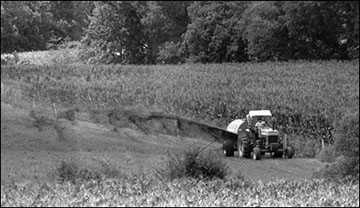 Figure 4
This tank-type applicator is broadcasting slurry onto the soil surface.
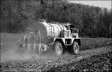 Figure 5A
This self-propelled, tank-type applicator is equipped to inject slurry below the soil surface, thus reducing nutrient losses and odor emissions.
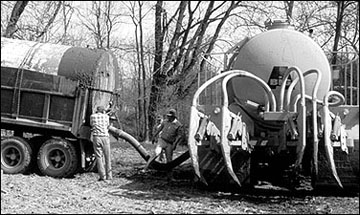 Figure 5B
The self-propelled, tank-type applicator shown in Figure 5A is being refilled from a tender truck.
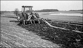 Figure 6
This drag-hose applicator can inject liquid and slurry below the soil surface.
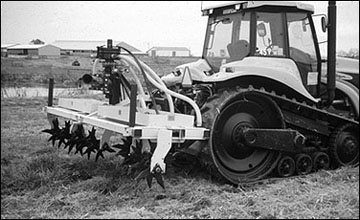 Figure 7
The aggressiveness of this incorporating applicator can be increased by angling the tine shaft.
An open-impeller centrifugal pump capable of handling large solids up to 1 inch in diameter may be selected for pumping livestock slurry to minimize clogging problems. Open impeller pumps may handle liquids with solids content up to 15 percent. They often have a sharp rotating blade at the pump inlet to chop large material such as bedding, hay, or silage.
Used for liquids with high solids content, foot valves can leak, thus requiring re-priming of centrifugal pumps used for livestock waste. To avoid priming problems, install the pump below the reservoir level. To reduce the risk of overland flow in case of a piping failure, the pump may be installed in a dry well.
Irrigating high-fiber slurry may require large sprinkler nozzles to prevent clogging. More details on pumps and irrigation can be found in the following section on applying lagoon effluent.
Injector-type applicators (either tanker mounted or tractor-mounted and hose-fed) usually have chisels or sweeps spaced at least 20 inches apart on a toolbar. Use of wide sweeps for injection results in a more uniform application of manure than knives. Generally, injecting with wide sweeps operating 4 to 5 inches below the surface takes less fuel and may have an advantage in sandy soils to place the nutrients near the root zone to minimize leaching. Knife injectors may have an advantage in heavy soils if subsoiling is needed to break up a clay pan. Large amounts of manure applied in a knife channel a short time before planting may result in damage to seedling root development.
Some injectors have paired disks or other furrow closing or covering devices to lessen the chance for odor emission or erosion of the slurry from the slot. Manufacturers are striving to develop applicators that create minimal disturbance of sod or residue cover (to aid in soil conservation compliance). Each opener may require from 10 to 30 or more horsepower, depending on soil, depth, opener design and speed.
The incorporating-type applicators mix the slurry with the surface soil layer using rotating spikes (e.g., an Aer-Way type, Figure 7) or knives (e.g., a rotary tiller). These applicators may take considerably less power than the injector-type, depending on the degree of incorporation. More odor may be emitted from incorporated manure than from injected manure.
Liquid manure and lagoon effluent
Land application by sprinkler irrigation or by a drag-hose, tractor-mounted applicator are the current practical methods of transporting and applying large volumes of lagoon effluent or ponded lot runoff. Drag-hose applicators can decrease odor problems and the loss of ammonia nitrogen to the air by incorporating the manure. The advantages of irrigation include reduced cost and lower power and labor requirements. However, land application of manure slurry and lagoon effluent with irrigation equipment requires a higher level of management than other methods of spreading in order to avoid pollution and nuisance problems. Labor costs are reduced by permanently installed underground pipes to sprinkler risers, center-pivot irrigators or hose attachment points for traveling guns or drag-hose applicators.
Pump selection
- Solids size and content and the required pumping pressure and flow rate are major factors in selecting a waste-handling pump. Fewer pumping problems result if solids are settled out (as in a lagoon), mechanically separated, or if dilution water is added (as by rain on a lagoon or feedlot). Semi-open impellers can handle water with small solids, such as swine lagoon liquid. Large closed-impeller pumps are efficient for high-pressure application of effluent without solids, such as municipal lagoons and others where the solids have been settled or separated out.
- Pressure requirements vary considerably with the application — sprinkler irrigation requires high pressures, typically from 40 to 120 psi at the sprinkler, depending on the nozzle diameter. Towed-hose, tractor-drawn applicators require sufficient pressure to overcome the friction losses in the conduit from the intake of the conduit to the applicator and in the applicator manifold. Many custom pumpers of livestock lagoons use a hydraulically driven, submersible chopper pump to feed a centrifugal booster pump at the side of the lagoon (Figure 8). This system eliminates priming and inlet screen problems.
- Solids content of livestock waste varies with livestock type, housing, and waste collection system. Table 4 shows the typical solids content for various liquid livestock waste handling systems. Figure 1 shows the relative handling characteristics of different types of manure and percent total solids for various species.
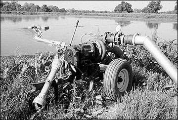 Figure 8
This PTO-powered, high-pressure centrifugal pump fed by a submersible chopper pump, is typical of pumps used with irrigation systems and drag-hose applicators handling slurry manure.
Table 4
Solids content for various liquid manure handling systems.
| System | Solids content |
|---|---|
| Manure pit | |
| Swine | 4 to 8 percent |
| Cattle | 10 to 15 percent |
| Holding pond | |
| Pit overflow | 1 to 3 percent |
| Feedlot runoff | less than 1 percent |
| Dairy barn washwater | less than 1 percent |
| Lagoon, single or first stage | |
| Swine | 1/2 to 1 percent |
| Cattle | 1 to 2 percent |
| Lagoon, second stage | Less than 1/2 |
Irrigation pumps for liquid wastes
Effluents from manure lagoons, feedlot runoff holding ponds, and milkhouses (less than 4 percent solids content) can often be handled by conventional irrigation pumps and equipment. Large quantities of these wastes are usually encountered in a system. Pipeline transport is most common because it is impractical to transport such highly dilute manure by tank wagon or truck. Single-stage, standard closed-impeller centrifugal pumps work well. Semi-open impeller pumps are sometimes desirable to reduce clogging. Large solids should be screened out at the pump inlet. The screen area should be as large as possible to minimize velocities into the screen and to eliminate plugging. A trash guard with a 5- to 15-foot radius encircling the screen is often beneficial. The guard can be constructed with small-diameter woven or meshed wire. When large sprinkler nozzles are used, most operators float the intake 18 to 24 inches below the surface and do not use an intake strainer (Figure 9). This keeps the intake free of floating debris, and above the sludge layer at the bottom of the lagoon. The pump should be located as far as is practicable from the inlet pipe to a livestock lagoon. If the lagoon is located in an area where there is a prevailing wind direction, the pump should be located on the upwind side of the lagoon since solids tend to migrate to the downwind side by wind and wave action.
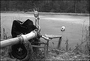 Figure 9
To prevent intake of floating debris, suspend an irrigation pump intake about 2 feet below the surface of a lagoon.
Swine, beef and dairy manure as excreted contains about 10 to 12 percent solids, whereas sheep and poultry manure contains about 25 percent solids. To be pumped with conventional irrigation pumps, the solids content should be diluted to 4 percent or less. Because of dilution from rainfall, water (effluent) pumped from lagoons typically contains less than 1 to 2 percent solids and presents no special pumping problem if no large or fibrous solids are present. If long, fibrous solids are present in the liquid being pumped, a chopper pump may be required (Figure 10). The larger the pump size, the larger the solid particles it can pump.
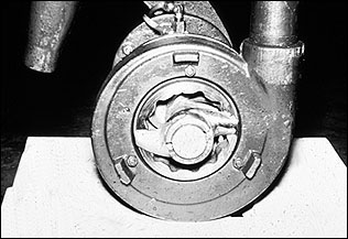 Figure 10
Chopper blades on the intake of a centrifugal pump.
Positive displacement helical screw pumps can handle liquids with high solids content, but they must be free of hard abrasive solids such as nails, sand or stones. Do not operate these pumps dry. A common practice is to add a small stream of fresh water directly into the pump inlet to ensure lubrication during operation. With positive displacement pumps, monitor line pressure when sprinkler irrigating directly out of liquid manure pits. If irrigation nozzles clog, pressure buildup can burst pipes.
Some high-capacity centrifugal pumps have two discharges, one to fill a tanker, the other a nozzle to agitate a pit or lagoon to suspend the solids (Figure 11). All-steel pumps are less susceptible to corrosion than pumps with brass impellers. Flushing the system with clean water after use prolongs equipment life by reducing corrosion. Table 5 shows data on several common types of manure pumps.
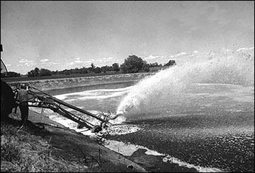 Figure 11
This PTO-powered, high-capacity pump can either fill tankers or bypass effluent to agitate a lagoon, or both.
Table 5
Typical manure pump characteristics.
| Pump type | Maximum solids content | Pumping rate | Pumping head, feet of water | Power requirements | Applications |
|---|---|---|---|---|---|
| Centrifugal | |||||
| Open and semi-open impeller | |||||
| Vertical shaft chopper | 10 to 12 percent | 1000 to 3000 gpm | 25 to 75 | 65+ hp | Gravity irrigation Tanker filling Pit agitation Transfer to storage |
| Inclined shaft chopper | 10 to 12 percent | 3000 to 5000 gpm | 30 to 35 | 60+ hp | Earth storage agitation Gravity irrigation Tanker filling |
| Closed impeller | 4 to 6 percent | 500+ gpm | 200+ | 50+ hp | Sprinkler irrigation Recirculation |
| Helical screw | 4 to 6 percent | 200 to 300 gpm | 200+ | Sprinkler irrigation | |
| Self-loading tanker | |||||
| Centrifugal, open impeller | 6 to 8 percent | 200 to 300 gpm | N/A | 75+ hp | Tanker loading |
| Vacuum pump | 8 to 10 percent | 200 to 300 gpm | N/A | 50+ hp | Tanker loading |
Pipelines
As a general rule, pipelines should be sized to limit fluid velocities in the pipe to 5 fps (feet per second) to reduce water hammer and excessive friction losses. Size pump suction lines so that velocities are less than 2 to 3 fps. Table 6 shows capacities and friction loss for various pipe sizes based on maximum velocity of 5 fps.
Table 7 contains friction loss data for portable aluminum pipe with couplings at 30 foot intervals and for PVC pipe. For 20-foot lengths of aluminum pipe, increase values by 7 percent. Table 8 lists recommended pipe sizes for various flow rate ranges.
Table 6
Friction loss in feet of head per 100 feet of pipe for flow rates with velocities limited to 5 fps.
| Pipe size** @ gpm | Friction loss in feet of head for pipe material* | ||
|---|---|---|---|
| Steel | Aluminum | PVC | |
| 4 inch @ 200 | 4.4 | 3.1 | 2.1 |
| 6 inch @ 400 | 2.7 | 2.0 | 1.3 |
| 8 inch @ 750 | 1.7 | 1.2 | 0.8 |
| 10 inch @ 1200 | 1.4 | 1.0 | 0.7 |
| 12 inch @ 1750 | 1.2 | 0.8 | 0.5 |
*To convert head in feet of water to pounds per sq inch (psi), multiply feet by 0.43. To convert psi to feet of head, multiply psi by 2.31.
**Nominal inside pipe diameter.
Table 7
Friction loss, feet of head per 100 feet of pipe.
| Flow rate | 4-inches | 6-inches | 8-inches | 10-inches | 12-inches | |||||
|---|---|---|---|---|---|---|---|---|---|---|
| Aluminum | PVC | Aluminum | PVC | Aluminum | PVC | Aluminum | PVC | Aluminum | PVC | |
| 100 gpm | 0.90 | 0.60 | ||||||||
| 150 gpm | 1.80 | 1.20 | 0.20 | 0.20 | ||||||
| 200 gpm | 3.00 | 2.10 | 0.40 | 0.30 | 0.1 | 0.1 | ||||
| 250 gpm | 4.80 | 3.20 | 0.60 | 0.40 | 0.1 | 0.1 | 0.1 | |||
| 300 gpm | 6.20 | 4.30 | 0.80 | 0.60 | 0.2 | 0.1 | 0.1 | |||
| 400 gpm | 10.6 | 7.20 | 1.50 | 1.00 | 0.3 | 0.2 | 0.1 | 0.1 | ||
| 500 gpm | 17.1 | 11.4 | 2.40 | 1.60 | 0.6 | 0.4 | 0.2 | 0.1 | 0.1 | 0.1 |
| 750 gpm | 36.3 | 24.1 | 5.00 | 3.40 | 1.3 | 0.8 | 0.4 | 0.3 | 0.1 | 0.1 |
| 1,000 gpm | 61.8 | 41.1 | 8.60 | 5.70 | 2.1 | 1.4 | 0.7 | 0.5 | 0.3 | 0.2 |
| 1,250 gpm | 93.3 | 62.1 | 13.0 | 8.60 | 3.2 | 2.1 | 1.1 | 0.7 | 0.4 | 0.3 |
| 1,500 gpm | 130.7 | 87.0 | 18.2 | 12.1 | 4.5 | 3.0 | 1.5 | 1.0 | 0.6 | 0.4 |
| 1,750 gpm | 173.9 | 115.7 | 24.2 | 16.1 | 6.0 | 4.0 | 2.0 | 1.3 | 0.9 | 0.6 |
| 2,000 gpm | 222.5 | 148.1 | 31.0 | 20.6 | 7.7 | 5.1 | 2.6 | 1.7 | 1.1 | 0.7 |
Source
Livestock Waste Facilities Handbook, MWPS18, Table 8-2.
Note
Flow rates below the values in boldfaced type for each pipe size exceed the recommended 5 feet per second velocity.
Table 8
Recommended pipe sizes for ranges of flow rates in gallons per minute.
| Pipe diameter | Aluminum | PVC | ||
|---|---|---|---|---|
| Flow rate range* | Maximum** | Flow rate range* | Maximum** | |
| 2 inches | 0 to 25 | 35 | 0 to 30 | 40 |
| 3 inches | 25 to 80 | 100 | 30 to 90 | 115 |
| 4 inches | 80 to 170 | 200 | 90 to 200 | 245 |
| 5 inches | 170 to 300 | 370 | 200 to 350 | 440 |
| 6 inches | 300 to 480 | 600 | 350 to 575 | 715 |
| 8 inches | 480 to 1000 | 1250 | 575 to 1225 | 1525 |
| 10 inches | 1000 to 1900 | 2300 | 1225 to 2200 | 2740 |
| 12 inches | 1900 to 3000 | 3800 | 2220 to 3560 | 4440 |
* Flow rate range was calculated based on a maximum pipe friction loss of approximately 1 psi per 100 feet of pipe.
**Maximum flow rate was calculated based on a maximum pipe friction loss of approximately 1.5 psi per 100 feet of pipe.
Note
This table provides general guidelines only. Larger pipe size may be required to keep total operating pressure within reason for long lengths of pipeline or large elevation differences between the pump and the application area.
Hoselines
Custom operators of traveling guns and drag-hose applicators frequently use feeder hoses in lieu of rigid pipe for ease in loading the conduit for transport with a reel rather than loading pipe onto a trailer (Figure 12). Because of the high cost of hose, operators may tolerate higher pressure losses with hose than with pipe. Estimated pressure losses due to friction are shown in Table 9. Traveling guns may use either a soft hose or a hard hose. Hard-hose travelers are more convenient for fields with varying lengths of travel but have higher friction losses with a given hose diameter.
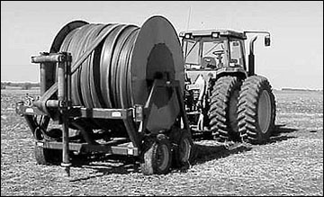 Figure 12
Hose carts provide a compact, fast means to transport, lay out and take up flexible drag hose or feeder hose.
Table 9
Estimated pressure loss in psi (due to friction) for 100 feet of soft hose* per 100 feet of hard hose**.
| Flow | Nominal inside diameter in inches | ||||
|---|---|---|---|---|---|
| 2.5 | 3.0 | 4.0 | 4.5 | 5.0 | |
| 100 gpm | 1.6/2.8 | ||||
| 150 gpm | 3.4/6.0 | 1.4/2.5 | |||
| 200 gpm | 5.6/10.2 | 2.4/4.2 | |||
| 250 gpm | 3.6/6.2 | 0.9/1.8 | |||
| 300 gpm | 5.1/8.8 | 1.3/2.4 | 0.6/1.2 | ||
| 400 gpm | 2.3/3.7 | 1.3/2.1 | |||
| 500 gpm | 3.5/5.8 | 2.1/3.2 | 1.1/1.9 | ||
| 600 gpm | 4.9/8.0 | 2.7/4.5 | 1.6/2.7 | ||
| 700 gpm | 3.6/6.0 | 2.1/3.6 | |||
| 800 gpm | 4.6/7.7 | 2.7/4.6 | |||
| 900 gpm | 3.4/5.9 | ||||
| 1,000 gpm | 4.2/7.0 | ||||
* Estimated loss when operated at about 100 psi, contact the manufacturer for more accurate data. Some operators add about 10 percent to the soft hose pressure loss for pumping slurry to an injector because of less hose expansion at less than 100 psi.
** Estimated loss, values vary due to differences in inside diameter, contact the manufacturer for more accurate data.
Calculating pump horsepower
Pump power requirements are determined by flow rate, pump efficiency and total head (the sum of total lift, friction losses, and the required pressure at the irrigator, expressed in feet) as follows:
Horsepower = (gpm x total head in feet) / (3960 x pump efficiency (decimal)
Example
You want to calculate the power required for a traveling gun with 90 psi (208 feet) pressure at the discharge (at the nozzle) operating 40 feet above the lagoon water surface at 700 gpm flow rate with total pipe friction losses for 3,000 feet of 8 inches x 30 feet aluminum pipe at about 35 feet (or 15 psi) and hose friction for a hard hose 4.5 inches x 1200 feet at 72 psi (or about 166 feet). Assume the pump efficiency is 70 percent.
Horsepower = (700 gpm x (208 + 40 + 35 + 166 = 449)) / (3960 x 0.70 pump efficiency) = 113.4 horsepower
Note
If the pump is operating near the water level, almost the entire 449 feet of head will apply at the pump discharge, subjecting the pipe to about 194 psi pressure, which may exceed the pressure rating of the pipe. If so, the pumping rate may have to be reduced to a point where the pipe will tolerate the operating pressure. This will result in a smaller coverage by the gun; thus, the travel lane spacing must be reduced.
Sprinkler systems
Although the equipment required for pumping and distributing lagoon effluent may be similar to conventional irrigation equipment, the smaller volume of water handled in most livestock lagoons generally allows the use of smaller and less costly systems. The type of sprinkler system chosen may depend on the particle size of the solids in the waste. The system capacity and type selected may depend on the capital available and the annual time window and labor available for pumping. Table 10 shows the estimated annual lagoon pumpdown time in hours for various animal species and systems. Table 11 gives the labor requirement and the number of sets for sprinkling 10 acres with various systems.
Table 10
Pumping time required to irrigate the annual average pumpdown volume for lagoons.
| Animal type and capacity | Volume acre-inches per year | System flow rate gpm | Average pumping time hours | Pipe size (aluminum) inches |
|---|---|---|---|---|
| Beef, total confinement, per 100 head | 5.0 | 100 300 500 |
22.5 7.5 4.5 |
3 to 4 5 6 |
| Beef, open dirt lot, per 100 head | 19.0 | 100 300 500 |
85.5 28.5 17.1 |
3 to 4 5 6 |
| Swine, total confinement, per 1,000 finishing hogs | 16.0 | 100 300 500 |
72.0 24.0 14.4 |
3 to 4 5 6 |
| Dairy, per 100 cows | 28.0 | 100 300 500 |
126.0 42.0 25.2 |
3 to 4 5 6 |
| Poultry, total confinement, per 10,000 layers | 3.6 | 100 300 500 |
16.2 5.4 3.2 |
3 to 4 5 6 |
Table 11
Labor and number of sets for 10 sprinkled acres.
| System | Number of sets per 10 acres | Labor per set | Labor per 10 acres |
|---|---|---|---|
| Hand-move 1/4-mile lateral with 60 feet between sets |
5.5 | 70 minutes | 6.4 hours |
| Stationary big gun 350 feet wetted diameter |
4.5 | 70 minutes | 5.2 hours |
| Traveling big gun 350 feet wetted diameter and 1/4 mile travel |
1.0 | 60 minutes | 1.0 hours |
Source
Livestock Waste Facilities Handbook, MWPS18, Table 9-8.
Hand-move sprinkler systems
The simplest and least costly sprinkler systems are the hand-carry or hand-move types that require labor input for setting up and moving the system. These systems usually have a 4-inch or 6-inch mainline pipe with one or more laterals, which tee off the main line at appropriate intervals. The laterals are assembled from 20-, 30-, or 40-foot sections of aluminum pipe and with sprinklers that cover 60- to 80-foot circles.
As the pump runs, a strip is sprinkled as long as the lateral and as wide as the cover diameter of an individual sprinkler. That strip is one set. After that set is irrigated, the pump is shut off and the pipe is disassembled, moved to a new location, reassembled, and the new set is sprinkled.
With a typical system, a 1/4-mile lateral covers 1.8 acres with each 60-foot move; 32 sprinklers can discharge 10 gpm each for a total 320 gpm pumped through 5-inch pipe. The application rate is 0.4 inch per hour and the power required is about 20 hp.
Advantages
- Low initial investment; consider a used system.
- Few mechanical parts to malfunction.
- Low power requirement (50 psi at the sprinklers).
- Adaptable to field shape. Different lengths can be set and run in any direction to get isolated corners.
Disadvantages
- High labor requirement; individual pipe sections are moved, which can be an unpleasant task with manure (Figure 13).
- Small sprinklers can plug.
Nozzle sizes for these systems are generally in the 1/2 to 1-inch range (Figure 14) and typically cover 1/2 to 2 acres per sprinkler depending on nozzle size and system operating pressure. Although labor input is required, these systems may be applicable for small lagoons (Figure 15).
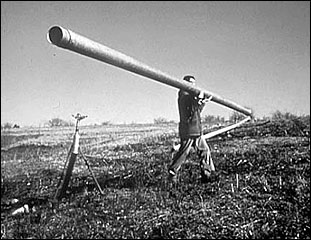 Figure 13
The use of aluminum pipe requires more labor than flexible hose requires.
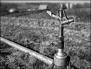 Figure 14
Small sprinklers (up to 3/4-inch diameter) can be used to irrigate lagoon effluent onto irregularly shaped fields.
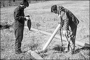 Figure 15
Small hand-set sprinklers require more labor than other systems but may be more economical for small operations.
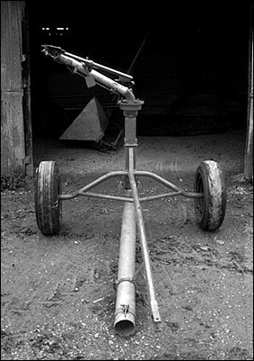 Figure 16
Stationary big gun on wheels to facilitate moving.
Stationary big gun
This system is applicable to many waste disposal systems. The system includes a pump and a main line similar to the handmove system, but with one or more large volume gun sprinklers replacing small hand-move sprinklers. Advantages of the big gun system include larger flow rates and a larger wetted area so less labor is required in moving the sprinkler. Some big guns are wheel mounted to facilitate moving the unit (Figure 16). Stationary big guns typically have nozzle sizes ranging from 1 to 2 inches, and operate best at pressures of 80 to 120 psi. Coverage areas of 2.5 to 6.0 acres can be obtained with proper selection of nozzle size and operating pressure. Although stationary big guns cost more than smaller hand-carry systems, the reduced labor cost and higher flow rates may offset the higher cost.
A typical big gun discharging 330 gpm sprinkles a 350 feet diameter circle (2.2 acres) at 0.33 inch per hour and 90 psi. The power requirement is about 30 hp.
Advantages
- Few mechanical parts to malfunction.
- Few plugging problems with large nozzle.
- Flexible with respect to land area.
- Pipe requirements are slightly less than with small sprinklers.
- Moderate labor requirement.
Disadvantages
- Moderate to high initial investment.
- High power requirement (90 psi at the sprinkler).
- Uneven distribution in windy areas.
Sprinkler systems require labor for movement from one set or location to another to ensure that the soil does not become saturated.
Traveling big gun
The traveling big gun is justifiable on large acreages irrigated several times a year. A single conventional gun sprinkler is mounted on a running gear that is pulled across the field. This self-propelled unit covers larger areas than stationary sprinklers of the same size and has variable speeds to control application depths. Generally, a water-driven winch on the machine pulls the traveling gun across the ground by a cable anchored at the end of the field (a soft-hose traveling gun, Figure 17), or the gun is pulled by a hard hose feeding the water to the traveling gun. A small engine may also drive the winch (on some models). Such an arrangement prevents solids from plugging the water turbine. However, plugging problems are minimal when pumping effluent from properly sized and operated lagoons. An engine-driven cable winch on a soft-hose traveler can be mounted on the traveler or anchored at the far end of the field.
Effluent is usually carried from the lagoon to the point of attachment in the field by portable aluminum pipe (Figure 18) or underground plastic pipe. Traveling guns require pressure ranging from 75 to 120 psi with flow rates from 100 to 800 gpm. Pressure required at the pump may range from 80 to 200 psi, normally being higher for hard-hose travelers than for soft-hose traveling guns. Soft-hose traveling guns usually travel either 660 feet or 1320 feet on each set. The hose is a major cost item on a traveling gun. Typical coverages range from 4 acres per set for small traveling guns to 13 acres per set for large traveling guns, depending on nozzle diameter, operating pressure, sprinkler angle and hose length.
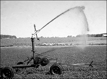 Figure 17
Soft-hose traveling big gun irrigators are frequently the system of choice for land application of lagoon effluent.
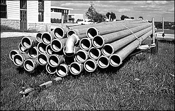 Figure 18
Portable aluminum pipe is available in a variety of sizes for use as a low-friction feeder conduit for irrigators and tractor-drawn, drag-hose applicators and injectors.
Large traveling guns are too costly for pumping typical livestock lagoons, unless also used for crop irrigation or for custom application of effluent. A common size irrigates 10 acres per set compared to about 2 acres for a stationary gun. Most manufacturers of traveling guns now make small units that are competitive in cost with the hand-move or stationary big gun sprinklers. These units are adaptable to the rolling terrain often encountered near lagoons and are easily transported.
Advantages
- Lower labor requirements other systems listed.
- Few or no plugging problems with large nozzle.
- Flexible with respect to land area.
Disadvantages
- Higher initial cost than the previous systems.
- High power requirement.
- More mechanical parts than the other systems, especially with an auxiliary engine.
Center-pivot irrigation systems
Center-pivot systems (Figure 19), which move around in a circle like the spokes of a wheel, have been used for some large livestock operations and are customarily used for irrigating effluent from municipal systems. Center-pivot irrigators are becoming more common for land application of livestock manure as the size of operations increases. Center pivots offer almost complete automation. Disadvantages include high initial cost, small sprinklers, and a fixed area of coverage. Systems with nozzles less than 1/4-inch diameter are not recommended because solids in the effluent could plug them.
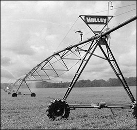 Figure 19
Center-pivot irrigator.
Source: Valmont Slurry Manager
In some cases, an irrigation reservoir also serves as the lagoon receiving livestock waste. In such cases, take care that the reservoir does not overflow, or that the overflow does not violate pollution laws and regulations.
If a lagoon and an irrigation reservoir are located close together, a properly designed pump intake system may allow simultaneous withdrawal of liquid from both the irrigation reservoir and the lagoon. If the irrigation water source and the lagoon are some distance apart, a pump at the lagoon will probably be required to inject the lagoon effluent into the pipe downstream from the pump serving the center-pivot system. This method may also be used to inject manure pit effluent into an irrigation system. Another alternative is to pump or drain the lagoon effluent into the irrigation reservoir provided there is sufficient volume available.
Special center-pivot systems are available with sequencing big guns for irrigating undiluted manure from pits and storage ponds.
Side-roll systems, which roll sideways across a rectangular field, are more adaptable than center-pivot systems but are limited to low-growing crops. Crop clearance is slightly less than half the diameter of the wheel at each lateral joint. Side-roll systems require rectangular fields and have small sprinklers and several mechanical devices to deal with.
Solid-set systems throughout a field are generally too expensive to install, except perhaps for small systems using small-diameter plastic pipe, or for year-round effluent disposal fields. The risers and sprinklers are always in place and must be avoided with machinery and protected from animals. Solid-set sprinkler systems are the most flexible and labor-saving of all systems. If automation is desired, remote control valves can be programmed to operate separate laterals or blocks in sequence.
Gated pipe systems (Figure 20) can provide low-pressure application at low cost and with low energy requirements. Labor requirements, however, may be high, and uniformity of application may be low.
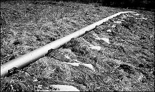 Figure 20
Gated pipe systems are occasionally fed by gravity from a lagoon at a higher elevation.
Application rate and depth:
Three performance characteristics are critical to proper land application of wastewater by irrigation. These performance characteristics are determined by site conditions and requirements as shown in the table that follows.
| Performance characteristic | Determined by |
|---|---|
| Sprinkler application rate | Soil infiltration rate or soil permeability |
| Depth of application per irrigation event | Soil water-holding capacity(depends on soil type and moisture content at time of irrigation) |
| Total depth of effluent applied annually | Amount of nitrogen or other limiting nutrient allowed annually under nutrient management plan |
Sprinkler application rate is a characteristic of sprinkler hardware and operating parameters (nozzle type, size, trajectory, pressure). Hence, sprinklers should be selected to be compatible with soil infiltration rate or permeability. If the sprinkler application rate is higher than the soil infiltration rate, the probability of runoff increases. Since runoff must be prevented when irrigating with wastewater, sprinklers are often selected for the lowest application rate possible.
The maximum allowable rate of application (inches per hour) to prevent runoff depends on the intake rate of the soil. The intake rate of an initially dry soil typically decreases at a high rate as water is added and approaches the permeability of the soil. County soil surveys give the permeability of soils in inches per hour and the available water-holding capacity in inches per inch. Contact your local Natural Resources Conservation Service office for a current soil survey.
Depth of application per irrigation event should be matched to the water holding capacity of the soil. The total amount (inches) of an application depends on the water holding capacity (moisture deficit) of the soil at the time of application.
Exceeding the water-holding capacity of the soil can result in runoff and contamination of surface water or percolation into groundwater. Depth of application is determined by duration of operation in the case of stationary sprinklers, and by travel speed in the case of traveling sprinklers.
The total depth of effluent applied annually should provide the target amount of nutrients to the receiving management plan area. This may be accomplished in a single irrigation event, or may require several separate applications, depending on site conditions and annual depth of application. See MU publication EQ327 for more information about determining sprinkler application rate and the depth of application per irrigation event and calculating the total depth of effluent to be applied annually.
For further information
- Agricultural Waste Management Field Handbook, Part 651, National Engineering Handbook. 1992. Washington, D.C.: Natural Resources Conservation Service.
- Natural Resources Conservation Service, Missouri Specifications, USDA/NRCS, Columbia, Mo. 65201.
- NebGuide G95-1266-A. Environmental Considerations for Manure Application System Selection. 1995. Biological Systems Engineering Dept., University of Nebraska, Lincoln, NE 68583-0726.
- Rules of the Department of Natural Resources, Division 20 - Design of Small Sewage Works. Chapter 8, Design Guidelines, 10 CSR 20-8.020. 1989. Clean Water Commission, Missouri Department of Natural Resources, Jefferson City, Mo. 65102.