The purpose of this guide is to give information on collecting, storing and treating water from ponds for domestic use. Treated surface water may be the best solution for many Missourians.
How the system works
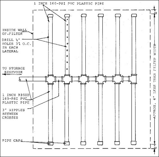
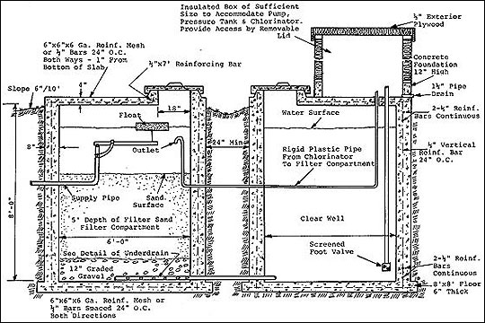
Water is collected from a clean drainage area and is stored in a pond or lake. It flows by gravity or is pumped to a sand filter compartment. The level of water in this compartment must be constant and can be controlled by a float. The water is filtered through sand to a gravel bed and collected in a pipe underdrain that moves it to a separate storage compartment called a clear well. See Figure 1.
A shallow well pump and automatic positive chlorinator are located in an insulated box on top of the clear well structure. The chlorinator is wired into the pump to operate when the pump operates. The chlorine is delivered by plastic pipe to the filter compartment. The pump and chlorinator may also be located in a nearby basement.
The sand collects foreign matter and the chlorine kills most bacteria present. There should be no more than 0.5 parts per million residual chlorine in the clear well. A chlorine test kit should be used to test this residual periodically.
Storage basin
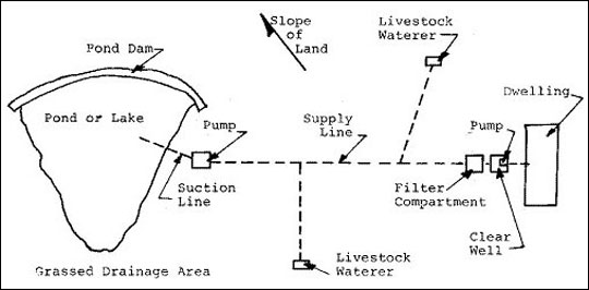
When the farm pond is constructed, the following are essential for domestic water supplies:
- Surface area should be 1/4 acre (11,000 square feet) or more. This ensures an adequate water supply.
- Depth should be at least 8 feet in the deepest part, and side slopes should be 3:1 or flatter.
- Aquatic growth at the edge of the pond should be kept to a minimum. One of the better ways to reduce aquatic growth is to limit the amount of nitrogen and phosphorus that enters the pond.
See Figure 2.
Drainage area
The drainage area should be about 10 times the surface area of the pond in claypan areas. More than this can be tolerated, but that will require more maintenance of the grassed spillway. In more porous soils runoff is less, so a greater drainage area would be desirable. A properly designed diversion or terrace can be used to add to or reduce the drainage area.
A buffer strip at least 100 feet wide from the edge of the water should be grassed and free of shrubs and trees and maintained free of livestock.
To obtain the best quality water, the total drainage area should be in grass used for hay production and maintained free of livestock. If any of the area is in cultivation, it should be terraced and water first run in a grassed waterway before entering the pond. Even then some silt will be carried into the pond, making filtering more difficult.
Runoff from livestock lots, domestic septic drain areas, county roads and similar areas should not enter the pond.
Care of water in storage
Water in the pond should be kept clear and free of silt and aquatic growth. If murkiness persists, add agricultural gypsum at the rate of 12 pounds per 1,000 cubic feet to aid in clearing the water. It can be spread over the water surface from shore or a boat. Add a few sacks at a time at intervals of a week until water clears.
Moss should not be allowed on the water surface. Moss can be controlled by using copper sulfate added at the rate of two ounces per 4,000 cubic feet or 2/3 of a pound per acre foot of water. Copper sulfate is the only chemical recommended by the Missouri Division of Health for controlling aquatic growth.
Preventing leaves, grass and other organic matter from entering the pond is desirable because they contribute to undesirable odor and color of the water.
Water from the pond
Location of the pond will determine whether water moves by gravity to the filter well or must be pumped. If the pond is below the elevation of the filter, locate a simple shallow well pump about 5 feet above the spillway level so suction will operate the automatic air control unit to prevent waterlogging.
The shallow well pump near the pond puts the water under pressure for delivery to various units such as a tank in a pasture, livestock water in a barn, to the garden for irrigation, etc. This water is also delivered to the sand filter unit. All outlet valves into stock tanks must be of the non-siphoning type to prevent stock tank water from flowing back into the supply lines should the pump fail to operate.
The pump at the clear well forces the filtered chlorinated water into the home and into the dairy milking parlor or food processing area. Other uses of this filtered chlorinated water should be limited.
In some situations it will be possible and advisable to build the filter unit at a lower elevation than the pond. In these instances the water will flow to the filter unit, making the first pump unnecessary. Also, the inlet in the pond will not require a foot valve. However, the first pump may be necessary to meet the unfiltered water needs of the farmstead.
Intake of water from the pond
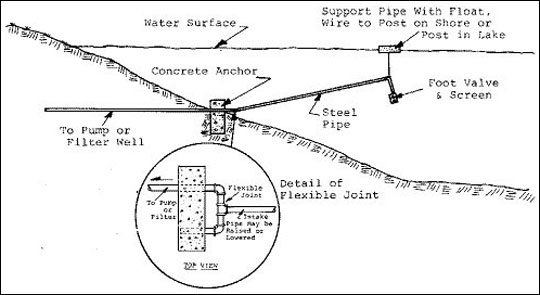
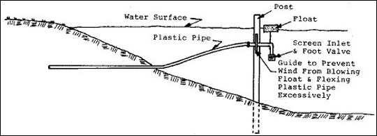
Water near the pond surface contains more oxygen and is of higher quality than water near the bottom. The intake to the system should take water from as near the surface as possible. Figure 3 and Figure 4 show ways of making inlets. Water from near the bottom of the pond is often dark and is devoid of oxygen. It has an undesirable odor and will reduce life of the sand filter.
Where a steel pipe is used for suction line, an elbow and tee arrangement allows line extending out into the pond to be moved up or down as needed for various elevations of the water surface. The outer end of the pipe may be supported by wire to a post in the water, a wire from a post on the shore or a float. During the summer months the outer end of the pipe can be near the water surface. During the winter all parts of the pipe must be 18 inches below the surface.
In order to prime a pump above the water level, a foot valve is needed at the intake so that the line from the water level to the pump can be filled. All pipes should be 18 inches below the water surface during the winter months to prevent freezing.
Building the filtering unit
The exact procedure for building the filter and clear well will depend on local conditions. The following procedure is suggested because it makes maximum use of locally available equipment.
Excavate trench with a bulldozer 8 feet deep and at least 12 feet wide and 20 feet long. Form and pour floors. Make a groove in the floor where walls will set and set 12-inch-long vertical reinforcing bars or pieces of steel at 4-foot intervals to make permanent water-tight joints between walls and floor.
There will be a 4-inch ledge around outer edges of floor. Regular basement forms may be used to form and pour walls. Tops of walls should be grooved and reinforcing bars extended 3 inches above the walls so that a permanent waterproof bond can be secured between top and walls.
Use empty cans or other means to form openings for pipes through walls.
After the concrete in the walls has set, remove the forms. Then form and pour the top with an 18 x 24 inch access opening. The lid and top arrangement makes a waterproof permanent cover as shown in Figure 5.
Place 12-inch-long vertical steel in the top over the clear well to anchor the foundation for the pump compartment.
After all the concrete work has been completed, install pipe through the walls and use mortar to make a water-tight seal. Complete backfilling and slope grade away from the filter unit at least 6 inches for 10 feet on all sides. Seed the area to grass.
In some locations it will be advisable to excavate less than 8 feet. Mound the excavated dirt around the wells to give good drainage.
Capacity of filter systems
Large amounts of filtered water should not be used for irrigation of gardens, shrubbery, etc. nor for watering live stock because this overworks the filter and requires excessive maintenance. Unfiltered water is satisfactory for any of these uses. Unfiltered water under pressure can be delivered to desired locations with plastic pipe.
The filtering system in Figure 5 has a surface filtering area of sand equal to 36 square feet. The clear well has a storage capacity of 2,000 gallons. It should furnish up to 1,000 gallons of filtered water per day. Each individual in the family will use 50 to 100 gallons of water per day. Therefore this filter unit will supply water for most families with some to spare.
If a unit is planned to furnish water for a dairy mill house or other installation requiring large quantities of filtered water, allow a minimum of 1 square foot of sand filtering area for each 70 gallons of water used per day. Also allow two gallons of clear well capacity for each one gallon of water used per day. On this basis, observe that the clear well shown in Figure 1 is adequate for supplying 1,000 gallons of water per day, the sand filter unit would be adequate for quantities of water up to 2,500 gallons per day.
If desired, the sand filter unit may be reduced to 3 feet 10 inches square inside measurements with the same depth as shown and supply up to 1,000 gallons of water per day. In this sketch the sand filter unit was made the same size in the clear well for simplicity of construction. While the unit shown will cost somewhat more than a smaller one, results will be a slower filtering rate, better water and less maintenance. When a family has an ample supply of water at a low operating cost, they can enjoy the luxury of not having to skimp on the use of water in the home.
Filtering sand
Satisfactory filtration can be accomplished only when high-quality filtering sand is used. A silicon sand free from organic matter should be used. Also the following specifications should be followed when securing filtering sand. They sound complicated to most people but will be meaningful to a sand and gravel company whose business is to assemble sand or other aggregate to meet certain specifications.
Use a sand that has an effective size not less than 0.2 mm and not greater than 0.4 mm. It is usually specified as 0.3 mm. The effective size of a sample of sand is defined as the size of grain that is larger by weight than 10 percent of the particles in the sample and smaller by weight than 90 percent of them.
Use a sand that has a uniformity coefficient no greater than 2.5. The uniformity coefficient is defined as the ratio of the side of grain which has 60 percent of the sample finer than itself to the size which has 10 percent finer than itself.
In areas where it is not possible to purchase a sand having these specifications, a fairly good filtering sand can be obtained by screening clean silicon sand through an ordinary window screen with 18 openings per inch. In such cases, all the sand passing through the screen is used in the filter.
Gravel
The purpose of the gravel underlayer is to support the sand and prevent it from settling or shifting to the openings in the pipe underdrain, thereby plugging or flowing through them. The gravel should be graded — maximum size 1 inch and minimum 3/8 of an inch.
Pump and pressure tank
A simple shallow well pump with all controls and pressure tank is adequate to pull water from the clear well and force it to wherever it is needed. A positive feed chlorinator should be used in connection with the pump to run when the pump runs.
Shallow well pumps come in many sizes. A 1/3 to 1/2 horsepower unit with a 20-gallon pressure tank is quite adequate for most homes. A pressure tank smaller than 20 gallons should not be used because the pump and chlorinator will go on and off more frequently.
A 42-gallon pressure tank will enable 8 gallons of water to be used between the time the pump automatically stops and starts again. For a 20-gallon tank, less than four gallons could be used between stops and starts of the pump.
Minimum pressures should be: pump on at 20 pounds per square inch and pump off at 40 pounds per square inch. A more satisfactory pressure is: pump on at 30 pounds per square inch and pump off at 50 pounds per square inch.
Disinfectant
The most convenient disinfectant to use is the ordinary household bleach. Usual concentration is 5-1/4 percent. It is a competitive product and large quantities are manufactured and sold, therefore cost is low. Other materials can be used for larger systems but are not as convenient.
One gallon of a 5-1/4 percent household bleach is required to make approximately 5 gallons of a 1 percent solution.
System inspection
If the system will supply water for a Grade A dairy or home other than the home of the owner, inspection is necessary by the Missouri Department of Health. Inspection can be arranged by writing or calling your local county health unit, the Department of Health of the municipality making inspections for market with producers, or the Missouri Division of Health, Broadway State Office Building, Jefferson City, Missouri 65101.
Disinfection and continuous chlorination
When the facility has been completed, clean the walls of the clear well of all debris and scrub deposits from the walls. Discard the water and debris. Allow the pond water to flow into the filter and clear wells, then add 0.2 pounds of chlorine per 100 gallons of water to "shock chlorinate."
After a period of 4 to 6 hours, prime the clear well pump and completely fill the pressure tank with the chlorine water.
Warning
If a rubber air-water separator is in the pressure tank, do not fill with strong chlorine solution.
Then fill all lines by bleeding each faucet. Allow several hours of contact. Drain the pressure tank and connect the chlorinator set to deliver the proper amount of chlorine solution to disinfect the incoming water. Pump from clear well until the chlorine level has been reduced to approximately 5 milligrams per liter. Discharge the chlorinated water to the surrounding area (not through a septic tank or lagoon or on a lawn). Reconnect the supply line to the house, milking parlor, etc. and flush them. Within a few days, the system will be in equilibrium and the chlorinator setting can be adjusted as the test indicates. At equilibrium 0.5 milligrams per liter of residual chlorine should be found in the clear well to ensure low bacterial counts.
Chlorinator management
The chlorinator should be a positive displacement type and it must be checked periodically to ensure proper functioning and for chlorine solution supply.
Mix the chlorine solution and adjust the chlorinator according to the manufacturer's instruction. Chlorine solutions deteriorate gradually when standing. Fresh solutions must be prepared as necessary to maintain the required chlorine residual.
Test for chlorine residual at least once a week to ensure effective equipment operation and solution strengths. A test kit is supplied with every chlorinator.
Keep a dated record of solution preparation type and proportion of chlorine used and residual test results.
Sensing devices are available that will automatically shut off the pump and activate a warning bell or light when the chlorinator needs servicing.
Sand filter management
Eventually enough material will collect on the surface of the sand to prevent water from filtering through. When this happens, scrape and discard about 2 inches of sand and filtered material from the top of the filter. When approximately 10 inches of sand have been removed, replace with clean sand to the original sand depth of 4 feet.
Bill of material for two compartments
- Floor
-
2.4 cu. yds. concrete1
128 square feet 6-inch x 6-inch x 6-gauge reinforcing mesh or 180 feet 1/2-inch reinforcing bars
- Walls
-
10.3 cu. yds. concrete1
460 linear feet 1/2-inch reinforcing bars
- Top
-
1.2 cu. yds. concrete1
100 square feet 6-inch x 6-inch x 6-gauge mesh and 20 feet 1/2-inch reinforcing bars
or 140 - 1/2 reinforcing bars
- Filter sand
-
6.7 cu. yds. — approximately 9.5 tons
- Graded gravel
-
1.4 cu. yds. — Approximately 2 tons
- Miscellaneous
-
Pipes, underdrain, valves, float
Materials for pump house, etc. Secure as needed for particular job.
1Not more than 6 gallons of water per sack of cement, including water in the aggregate. Six bags of cement per cubic yard of concrete.