These criteria apply to the design of canopy and hood inlet spillways used as the principal spillway for ponds, irrigation reservoirs, and stabilization structures.
The canopy or hood inlet spillway usually is used in conjunction with an emergency spillway.
Canopy inlet
Description
Examples of the use of canopy inlet spillways are shown in Figure 1:
- To discharge water from terraces, grass waterways and diversions into a main drainageway.
- In grade stabilization structures, ponds or irrigation reservoirs.
The canopy inlet is formed by cutting the end of the conduit and welding an end-plate of suitable metal to the end of the conduit. The dimensions for construction of canopy inlets and the minimum entrance heads required to cause the conduit to flow full are given in Figure 2 and Table 1.
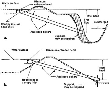
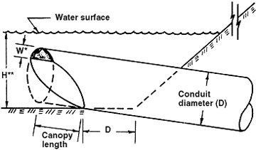
Table 1. Inlet dimensions. ("D" is conduit diameter.)
| Slope of conduit | W* - Plate width1 | Canopy length | H** - Minimum entrance head2 |
|---|---|---|---|
| 0 to 5 percent | 0.2D | 0.6D | 1.3D |
| 6 to 15 percent | 0.2D | 0.8D | 1.4D |
| 16 to 25 percent | 0.3D | 1.1D | 1.5D |
| 26 to 32 percent | 0.35D | 1.3D | 1.6D |
| 1. Plate width is measured from the valley of the corrugations on corrugated pipe and from the inside surface of smooth pipe. 2. Minimum entrance head required to cause the conduit to flow full. Place the emergency spillway at least this distance above the invert of the inlet. | |||
Adaptability
The canopy inlet spillway is particularly well adapted to controlling overfalls over 8 feet and to sites where a good emergency spillway or an appreciable amount of detention storage above the inlet can be provided.
Advantages
In comparison to the drop inlet, the canopy inlet has the following advantages:
- No riser is required.
- There is less excavation required if the structure is used at the ends of waterways or diversions to discharge water into a main drainageway.
- There is a lower fill over the conduit in grade stabilization structures using an earth embankment.
- It is simple to fabricate and install.
- It is low in first cost.
- It is less likely to be clogged with debris.
- Livestock and children are not likely to fall into it and be injured.
As compared to the hood inlet, the canopy inlet has the following advantages:
- The conduit will fill at a lower entrance head.
- Because a baffle is not required, it is simpler to fabricate and install and is less expensive.
Limitations
Canopy inlets require a greater depth of water over the inlet to obtain full conduit flow than do drop inlets. For larger-diameter conduits, a large difference in elevation between the conduit inlet and the emergency spillway is required if full flow in the conduit occurs before the emergency spillway functions.
Avoid this large difference in elevation by using a box inlet on the canopy inlet. (See discussion to follow in "Metal or concrete box inlet on the canopy or hood inlet" section.) It may however, be desirable at some locations to substitute a morning glory or drop inlet for the canopy inlet.
If high rates of flow are to be carried and a suitable emergency spillway cannot be constructed and there is limited detention storage, a large-diameter tube will be required. In this case, a flume or drop spillway may be better suited.
Design
If the canopy inlet is constructed to the dimensions given in Figure 2, the conduit will flow full when the water surface over the inlet reaches the depths indicated as "minimum entrance head." The difference in elevation between the bottom of the canopy inlet and the emergency spillway must equal, and in some cases exceed, the minimum entrance head.
Hood inlet
Description
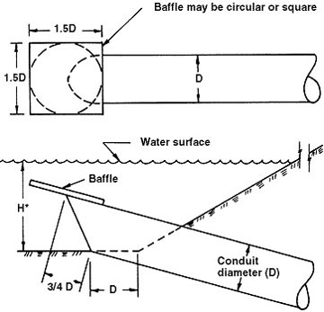
Examples of the use of hood inlet spillways are shown in Figure 1. The hood inlet is formed by cutting the end of the conduit and welding or bolting a baffle of suitable material to the conduit. The dimensions for constructing the hood inlet and baffle and minimum entrance heads required to cause the conduit to flow full are given in Figure 3 and Table 2.
Table 2. Minimum entrance head requirements
| Slope of conduit | H* - Minimum entrance head1 | ||
|---|---|---|---|
| 0 to 5 percent | 1.5D | ||
| 6 to 15 percent | 1.6D | ||
| 16 to 25 percent | 1.7D | ||
| 26 to 32 percent | 1.8D | ||
| 1. Place the emergency spillway at least this distance above the invert of the inlet. | |||
Design
If the hood inlet is constructed to the dimensions given in Figure 3, the conduit will flow full when the water surface over the inlet reaches the depth indicated as minimum entrance head. The difference in elevation between the bottom of the hood inlet and the emergency spillway must equal, and in some cases exceed, the minimum entrance head.
Metal or concrete entrance box for canopy and hood inlets
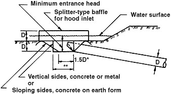
*1.5D = the minimum diameter for a circular box with sloping sides.
**The box may be either round or square. Use minimum dimension of 2D for the side if square, or 2.5D diameter if round.
For those installations where the depth of water that can be impounded over a canopy or hood inlet is less than the minimum entrance head, it may be advisable to lower the inlet by means of an entrance box so that the conduit will flow full (Figure 4).
The entrance box should be made of concrete if the conduit is concrete. Either metal or concrete may be used for the box if the conduit is metal. A concrete entrance box may be constructed with vertical sides, if forms are used, or the earth may be shaped to the desired dimensions and the concrete placed on the earth form.