Runoff from construction sites is the major source of sediment in urban areas under development. There are two main reasons construction activities increase pollutant loads in runoff. First, the volume and rate of runoff typically increase, providing a larger capacity to transport pollutants to rivers and lakes. Second, the vegetation is removed, leaving bare soil that is much more vulnerable to erosion, resulting in sediment moving into receiving waters. Typical sediment loading rates from construction sites vary from 100 to 200 tons per acre per year, but some areas can be considerably higher if no erosion control practices are implemented.
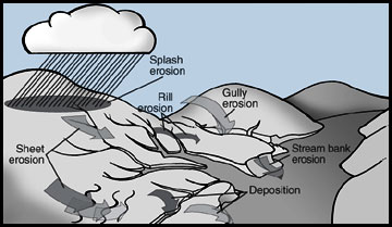
Raindrop impact is the major cause of soil particle detachment (Figure 1), which can result in the particles moving down slope in flowing water (as sheet erosion) during a rainfall event. Flowing water can also detach soil particles if the velocity is high enough, usually where water starts to concentrate (rill and gully erosion in Figure 1). If the velocity is reduced sufficiently, particles will settle out. The velocity at which settling begins is dependent on particle size and density, as is the time required for the particles to settle out. Large, dense particles, such as grains of sand, settle first. Fine clays settle out slowly and only in relatively still water.
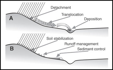
Erosion control measures can disrupt the phases of erosion by providing soil stabilization, runoff management and sediment control (Figure 2). By preventing splash, sheet and rill erosion, soil stabilization measures (such as soil amendments, vegetation, and mulch) can interrupt the first phase of the erosion cycle, the detachment of soil particles. Vegetative cover can provide effective soil stabilization, but sometimes the vegetation needs the extra stability and protection of additional measures such as erosion control blankets, silt fences, terraces, and diversions.
This publication discusses typical practices to reduce erosion and retain sediment on construction sites. Table 7 summarizes the effectiveness of basic erosion control practices. Erosion- and sediment-control structures should be installed and maintained in accordance with local jurisdictions, manufacturers’ specifications or engineering drawings.
Construction Site Inspection Form PDF
Vegetative cover
Vegetative cover is normally the most effective and practical control of erosion and sediment loadings but takes time for establishment. Sodding can reduce the time required for grass establishment and can be used to control erosion in some channels in lieu of riprap or concrete. The roots of vegetation, such as grass, binds soil particles together to resist erosion. Vegetation helps absorb the impact of raindrops to prevent detachment of soil particles. Vegetation can flatten and, like shingles on a roof, allow the runoff to flow above the soil. Stiff, standing vegetation can slow runoff (which may allow larger particles to settle out) and act as a filter to remove soil particles from flowing water.
Consider leaving vegetated strips in phased construction projects to slow runoff and trap sediment. These strips may have grass cover or woody vegetation. Vegetated cover may act as a filter strip at intervals down a slope or as a filter/buffer along a stream or body of water. Table 1 provides guidelines for minimum strip widths of grass or forest for various slopes.
Table 1. Recommended filter strip widths for various slopes.
| Slope of land | Width of filter strip (feet) | |
|---|---|---|
| % | Vigorous grass | Forest land |
| 0 | 10 | 25 |
| 2 | 12 | 29 |
| 4 | 14 | 33 |
| 6 | 16 | 37 |
| 8 | 18 | 41 |
| 10 | 20 | 45 |
| 15 | 25 | 55 |
Temporary vegetative cover
Disturbed construction sites should be seeded as soon as possible to provide economical erosion control. Annual plants which sprout rapidly and survive for only one growing season may provide adequate cover for up to 12 months. Plant materials, lime and fertilizer requirements, and seeding rates and times should be specified by as qualified professional. Table 2 has typical seeding rates if no plan is available. Fertilizer and lime, if needed, should be incorporated 3 to 6 inches into the soil. Soil should be tilled 3 inches deep for drilling or broadcast seeding. No-till drilling may be possible if the soil is not excessively compacted. Large seeds such as small grains should not be planted over 11/2 inches deep; small grass and legume seeds should not be planted over 1/2 inch deep. Mulching is recommended to conserve moisture and reduce erosion.
Table 2. Plant materials and minimum rates for temporary seedings.
| Species | Seeding rate | Plant characteristics | |
|---|---|---|---|
| lb/acres | lb/1000 ft² | ||
| Oats | 80 | 2 | Not cold tolerant, height up to 2 feet |
| Rye, wheat | 90–120 | 2–21/2 | Cold and low pH tolerant, height up to 3 feet |
| Millets, warm-season annuals, sudangrass | 45 to 60 | 1 to 11/2 | Aggressive growth, height up to 5 feet |
| Annual ryegrass | 75 | 2 | Not heat tolerant, height up to 16 inches |
| Tall fescue | 45 | 1 | Warm season legume, makes own nitrogen, tolerates low pH |
| If vegetative cover will be required for more than a year, consider adding fescue or another permanent species to the seeding mixture. | |||
Permanent vegetative cover
A perennial vegetative cover should be considered for sites where protection will be needed for more than 12 months. This practice is used where vegetation is desired to permanently stabilize the soil, e.g., to protect channels, dikes and embankments. As with temporary seedings, care is required to establish a good, thick cover of permanent grass. Stockpiling topsoil to be redistributed at the finish grading will aid in establishing a permanent vegetative cover. Legumes may be added to the seeding mix to provide nitrogen and to provide growth during hot, dry weather when some grasses are dormant.
Seedbed preparation and other cultural practices are similar for temporary and permanent seedings. Nurse crops, such as wheat or rye, may be added to the seeding mix to reduce weeds, control erosion and provide winter protection for seedlings. Plant materials, lime and fertilizer requirements, and seeding rates and times should be specified by a qualified professional. Table 3 shows typical seeding rates. Mulching is recommended to conserve moisture and reduce erosion.
Table 3. Minimum seeding rates for permanent seedings.
| Species | Seeding rate (PLS)* | |
|---|---|---|
| lb/acre | lb/1000 ft² | |
| Tall fescue | 80 | 2.0 |
| Reed canarygrass | 40 | 1.0 |
| Redtop | 8.0 | 0.2 |
| Perennial rye | 80 | 2.0 |
| Canada wild rye | 24 | 0.6 |
| Bromegrass | 100 | 2.3 |
| Crested wheatgrass | 16 | 0.4 |
| Rye, wheat (as nurse crop) | 1.0 | 1.4 |
| *PLS is pure, live seed. Example: If the sewed is 95 percent pure and has 90 percent germination, the PLS is 85.5 percent [0.95 x 0.90 = 0.855]. To calculate the amount of this seed to plant 80 pounds of PLS per acre would require 80/0.855 = 93.57 pounds per acre. | ||
Mulch
Natural mulch
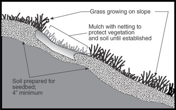
Natural mulch, such as straw and wood chips, and artificial mulch, such as geotextile (fabric) rollout blankets, are effective in absorbing raindrop impact to reduce soil detachment and are effective as soon as they are applied. Mulch is normally used in combination with seeding to provide ground cover during the establishment period for a temporary or permanent vegetative cover. Disadvantages of a strawlike mulch are that it can blow or wash away. Various binding agents (e.g., asphalt tackifiers) and netting are available to help hold straw in place (Figure 3). Netting and the blanket-type mulches described below can be pinned in place.
Geotextile erosion control blankets
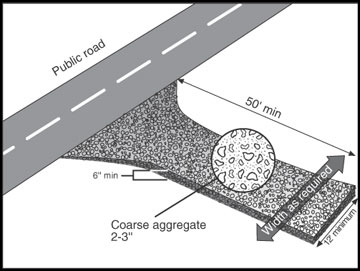
Some geotextile erosion control blankets are organic and biodegradable and can be used in combination with seeding to control erosion until a permanent vegetation is established. They can also be used to replace rock riprap or concrete in channels (green engineering). Other types of geotextile blankets are inorganic and nonbiodegradable. Some of these can be used in combination with seeding to control erosion until a permanent vegetation is established and to provide a permanent supplement to the seeding. Some types can be used as silt fences. Geotextile underlayment can be used on soft subgrades for both temporary graveled access to construction sites (Figure 4) and permanent gravel roads or as an underlayment for riprap and rock dams.
Soil amendments
Polymer soil amendments known as polyacrylamides (PAM) can help bind soil particles together to reduce erosion and sedimentation. When used on bare soil, without seed or mulch, anionic PAM should be used on slopes 3-to-1 or flatter. Polyacrylamides are not a cure-all, but they can be a good addition to other sound management practices. Both laboratory and field demonstrations of the effectiveness of PAM in Missouri show that they can significantly reduce loss of soil from agricultural and construction sites. Hydroseeding equipment used for seeding, fertilizing and mulching disturbed ground can be an effective way to deliver polyacrylamides.
Silt fence barriers
A silt fence is a temporary barrier of geotextile fabric (filter cloth) used to intercept sediment-laden runoff from small drainage areas. A silt fence can be used to promote sheet flow, to reduce runoff velocity, and to help retain transported sediment on the site, thus reducing erosion and enhancing water quality. The expected life span of a silt fence depends on the type of fabric used and its ultraviolet stability. Silt fences are usually installed on the contour with each end turned upslope, causing the runoff to form a pond.
Types of silt fence barriers
There are two general types of silt fence barriers — filter barriers and silt fences
Filter barriers
Filter barriers are inexpensive structures composed of burlap or standard-weight synthetic filter fabric attached to wooden or steel stakes. A typical specification for burlap is 10 ounces per square yard of fabric. Flow rates through burlap filter barriers are slightly slower and filtering efficiency is significantly higher than for straw bale barriers. The average useful life of synthetic filter fabric depends on the ultraviolet inhibitor added, but is typically three months.
Silt fences
Silt fences have a slower flow rate but significantly higher filtering efficiency than burlap fabric. Silt fences are effective in sheet flow conditions and usually ineffective with concentrated flows. Woven and nonwoven synthetic fabrics are available. Woven fabric usually is stronger and does not require the additional support of a wire mesh. Table 4 shows typical specifications for silt fence filter fabric. The average life span is about six months, depending on the ultraviolet inhibitor added.
Table 4. Typical specifications for silt fence filter fabric.
| Properties | Requirements |
|---|---|
| Filtering efficiency | 85 percent (minimum) |
| Tensile strength at 20 percent elongation (maximum) | Standard strength: 30 pounds per linear inch (minimum) Extra strength: 50 pounds per linear inch (minimum) |
| Slurry flow rate | 0.3 gallon per square foot per minute (minimum) |
Where silt fences are used
Silt fences are commonly placed at intervals on a disturbed slope or adjacent to streams and ponds. Silt fences have a lower failure rate than straw bale barriers but are more expensive. Silt fences can be used for slope protection, in minor swales or ditches, and around storm drains.
Slope protection
The maximum size of the drainage area should be 1/4 acre per 100 feet of fence; the maximum length of slope behind the fence is 100 feet. Table 5 shows the maximum length for given slopes. A silt fence may be used around or downslope of soil stockpiles and along the sides of streams and ponds.
Table 5. Allowable slope length above silt fences or straw barriers.
| Slope | Slope length (feet) |
|---|---|
| Less than 2 % | 100 |
| 2 to 5 % | 75 |
| 5 to 10 % | 50 |
| 10 to 20 % | 25 |
| Greater than 20 % | 15 |
| A silt fence may be used around or downslope of soil and along the sides of streams and ponds. | |
Channel/storm drain application
- Silt fences may be used in stream channels and storm drains for areas draining no more than 1 acre. They are not for use in perennial channels.
- Silt fences should be used only where runoff volume is not expected to exceed 1 cubic foot per second.
- Use burlap filter fabric, or better, a synthetic fabric.
Basic design and construction criteria
- The height of the filter fabric silt fence should be at least 11/4 feet and not exceed 3 feet.
- The filter fabric should be purchased in a continuous roll and cut to the length of the barrier to avoid use of joints.
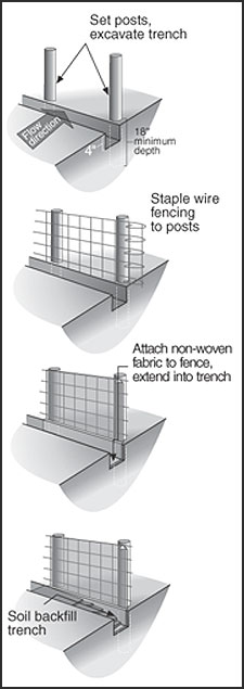
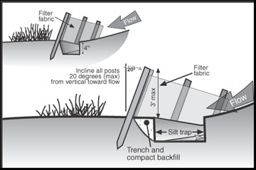
- Wood posts should have a minimum cross-sectional area of at least 3 square inches. Steel posts can be standard “T” or “U” sections weighing no less than 11/3 pound per foot, with projections for fastening wire mesh. Posts should be at least 5 feet long and driven at a slight upstream angle into the ground to a minimum depth of 18 inches (Figure 5).
- When a wire mesh support fence is used, the wire should be at least 14-gauge with maximum mesh spacing of 6 inches and must be securely fastened to the upstream side of the post.
- With extra-strength filter fabric, no wire mesh support is required, and maximum post spacing is 6 feet. Otherwise, wire mesh is required with a maximum post spacing of 10 feet.
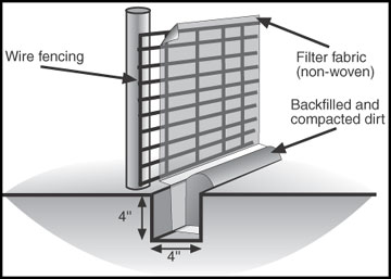
- A trench is excavated at least 4 to 8 inches deep and 4 inches wide along the line of the support posts and upstream from the barrier, as shown in Figure 5.
- The filter fabric and wire mesh (when applicable) are stapled or wired to the post and then placed at least 8 inches into the trench. Staples should be a 17-gauge wire and 1/2 inch long.
- The trench is backfilled and the soil is compacted over the filter fabric (Figure 6).
- When a filter barrier is constructed across a ditch or swale, the barrier should be long enough to eliminate end flow; the plan configuration should resemble a horseshoe with the ends pointing upslope.
Common trouble points
- Fence not adequately supported; this may be because of an excessive buildup of silt.
- Drainage area too large; divide drainage area into smaller areas.
- Too much sediment accumulation allowed before clean out; too much sediment accumulation may cause barrier to fail.
- Upstream slope too steep or too long; break up slope length with additional rows of barriers.
- Fence located across a drainageway; flows may exceed fence’s capability.
- Undercutting occurs; fence not buried 4 to 8 inches or trench not backfilled and compacted properly.
- Erosion around endpoints of barrier; they are lower than top of temporary pool; reshape ends to an elevation above pool level.
Straw bale barriers
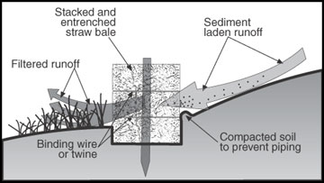
A straw bale barrier is a temporary entrenched and anchored barrier used to intercept sediment-laden runoff and to provide some retention of sediment from small drainage areas. A straw bale barrier can be used to promote sheet flow and to reduce runoff velocity, thus reducing erosion and improving water quality. The expected life span is normally three months, therefore straw bales must be replaced or a new barrier placed directly upslope of the old when a barrier is required for longer time periods. An average straw bale should be 30 inches long, weigh at least 50 pounds, and contain at least 5 cubic feet of material.
Where straw bales are used
Straw bales can be used for slope protection in disturbed areas to control sheet and rill erosion or in minor swales or ditches to trap sediment-laden runoff. Straw bale barriers may also be used around or downslope of soil stockpiles.
Slope protection
Recommended maximum size of the drainage area is 1/4 acre per 100 feet of straw bale barrier fence length; the maximum length of slope behind the fence is 100 feet; and the maximum slope length for given slopes is as specified in Table 5. These limitations are similar to those for silt fences. See Figure 7a for typical installation.
Channel application
- Straw bale barriers may be used for areas draining 1 acre or less.
- Straw bale barriers may be used where runoff water velocities will not exceed 2 cubic feet per second.
Basic design and construction criteria
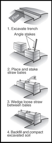
A trench 4 to 6 inches deep should be excavated to the length of the barrier and the width of the bale, as shown in Figure 7b. Excavated material should be placed on the upstream side of the trench. Wire or string-bound bales containing at least 5 cubic feet of either hay or straw are placed in the trench and should be anchored by two 2 x 2 wooden stakes or rebar steel pickets driven through the bale into the underlying soil at a slight upstream angle to help prevent the bale from overturning. The first stake should also be driven slightly toward the previously laid bale to force them together. Spacing between the bales should be tightly chinked with loose straw. The excavated soil can now be backfilled firmly against the upslope side and compacted.
For straw bale check dams in swales or ditches, place the barrier across the swale such that the ground level at the end of the bales is higher than the top of the lowest middle bale (Figure 7c). This will prevent scouring due to flow around the ends of the barrier.
Fiber rolls/logs
Fiber rolls (or logs) can substitute for straw bales or silt fences in some situations with a savings in labor to install. The rolls are typically 8 to 20 feet long and 8 to 20 inches in diameter. One vender includes five stakes with a 10-foot excelsior log, which can replace three straw or hay bales. The 10-foot log weighs 3 pounds per linear foot in a 12-inch diameter and 5 pounds per linear foot in an 18-inch diameter. Fiber rolls are more aesthetically pleasing, but the cost may be seven to eight times as much as a silt fence.
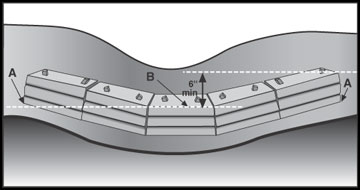
Temporary sediment trap
A temporary sediment trap is a control device used to intercept sediment-laden runoff and to trap sediment and prevent or reduce off-site sedimentation. A temporary sediment trap can be formed by excavation or by embankments constructed at designated locations accessible for cleanout (Figure 8).
Where temporary sediment traps are used
A temporary sediment trap may be located in a drainageway, at a storm drain inlet, or at other points of discharge from a disturbed area. They may be constructed independently or in conjunction with diversions. They may be used in most drainage situations to prevent excessive siltation of pipe structures. Designs may vary from a low-cost straw bale or silt fence to a more elaborate gravel and riprap structure.
Basic design and construction criteria
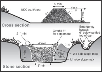
- A temporary sediment trap is used for drainage areas of 5 acres or less and has an expected life span of no more than two years.
- Earthen embankment height should not exceed 5 feet with a top width of at least 5 feet and side slopes of 2-to-1 or flatter.
- Generally, a spillway should be at least 11/2 feet deep and 4 feet wide (Figure 9). Table 6 provides a guide to spillway width requirements.
- A temporary sediment trap should not be located within 20 feet of a building foundation if the trap is to function during building construction.
- All sediment structures should be twice as long as they are wide.
Table 6. Spillway width criteria for construction.
| Drainage area (acres) | Spillway width at bottom (feet) |
|---|---|
| 1 | 4.0 |
| 2 | 6.0 |
| 3 | 8.0 |
| 4 | 10.0 |
| 5 | 12.0 |
Common trouble points
- Inadequate spillway size; this results in overtopping of dam, poor trap efficiency, and possible failure of the structure.
- Omission or improper installation of filter fabric (under riprap outlets); this results in washout under sides or bottom of the stone outlet section (piping).
- Low point in embankment caused by inadequate compaction and settling; this can result in overtopping and possible failure.
- Outlet not extended to stable grade; this can result in erosion below the dam.
- Stone size too small or backslope too steep; this may result in stone displacement.
- Inadequate vegetative protection; this can result in erosion of embankment.
- Inadequate storage capacity; the sediment is not removed from basin frequently enough.
- Contact slope between stone spillway and earth embankment too steep; piping failure is likely.
Maintenance
Inspect temporary sediment traps after each significant rainfall event and repair any erosion and piping holes immediately. Trap should be cleaned out when sediment reaches half the design depth; a stake set at the cleanout level is helpful. Gravel facing should be cleaned or replaced if clogged. Check spillway depth periodically to ensure at least 1½ foot depth.
Removal
Do not remove the sediment trap until all sediment-producing areas have been permanently stabilized. The accumulated sediment in the trap should be removed, and all excavation should be backfilled and properly compacted. Smooth the site to blend with the terrain or as specified on plans.
Table 7. Effectiveness of basic erosion control practices.
| Practice | Limitation | Advantage | Effectiveness |
|---|---|---|---|
| Reduce land disturbance | May increase construction cost. | Most effective in reducing overall soil erosion. | Up to 90% |
| Natural vegetative cover | Requires more planning; may constrict construction activities. | Self-anchoring to prevent erosion and runoff; provides for water infiltration. | 90% |
| Seeding and hydro seeding | Requires seedbed preparation and maintenance for establishing cover. | Self-anchoring to prevent erosion; stabilizes soil. | 50% |
| Temporary cover (mulch, straw, wood chips, etc.) | May require binder and general maintenance. | Immediate application; effective in reducing soil runoff. | 50% |
| Temporary — geotextile erosion blankets | Proper installation is a must. Fabric may degrade in sunlight. | Use in highly erodible areas; convenient. | Varied |
| Soil amendments (polyacrylamides, PAM) | Products may break down due to traffic and weather conditions. | Easy to apply; effective in stabilizing areas until plant growth occurs. | 30–90% |
| Silt fence, synthetic fiber or straw bales | Proper installation can be time consuming. Requires maintenance. | Removes sediments and prevents sediment from leaving site. | Up to 65–85% |
| Sediment trap | Requires cleanout and maintenance. Suitable for limited size area. | Simple to install; protects downstream areas from sediment. | 60–80% |
| Diversion — ridge, channel and combination | May require developing a channel; needs proper maintenance and establishing vegetative lining. | Very effective at controlling runoff and erosion. | Up to 50% |
| Check dam | May kill grass linings, reduce hydraulic capacity of the channel. | Easy to install; may be used as permanent design; high percent of sediment settles out; reduces velocity. | Up to 60–80% |
| Rock dam sediment basin | Slope and topography necessary for effective basin. Limited life span. | Efficient method of sediment control, reduces speed of runoff. | Up to 50–90% |
| Inlet protection | Difficult to remove collected sediment; practical only for low- sediment and low-volume flows. | Prevents clogging of existing storm drain systems; reduces amount of sediment leaving site. | Up to 65–85% |
Diversions
A diversion is a berm (dike or ridge) or a swale (excavated channel or ditch) used to prevent sediment-laden waters from leaving a site and to prevent off-site or upstream waters from entering a site. Typical diversions are a combination berm/swale and may be temporary or permanent structures.
Where diversions are used
- At the toe of cuts or fills to direct sediment-laden runoff to sediment traps.
- At the top of cuts or around disturbed areas to divert clean runoff until the disturbed areas are permanently stabilized.
- At the top of steep slopes where excess runoff would cause erosion problems.
- At selected intervals on long, sloping routes.
- Around a site to prevent entry of off-site runoff and to reduce flooding.
Temporary diversions
This practice applies wherever stormwater runoff from areas less than 5 acres must be temporarily diverted to protect disturbed areas and slopes or to retain sediment on site during construction. These structures generally have an expected life of 18 months or less and should be vegetated if expected to be left in place more than 30 days. Diversions should be designed by a registered design professional to handle the peak runoff from a 10-year storm. The channel grade should be positive toward the outlet but flat enough to produce nonerosive velocities. Outlets should be stabilized to prevent erosion and convey runoff to a point where it will not cause damage. Temporary diversions may be removed and blended with the natural topography when the area protected is permanently stabilized.
Permanent diversions
Permanent diversions are used wherever stormwater from less than 5 acres can be redirected to protect downslope structures or areas from erosion, sediment and excessive wetness or localized flooding. They are designed to intercept and carry excess water to a stable outlet, where it can be temporarily stored or released. Vegetation should be established on ridges and channels as soon as possible or use synthetic erosion control measures as specified in the design. Maintain vegetation with periodic fertilization and mowing to keep plantings in a vigorous, healthy condition.
Check dams
Check dams are small, temporary dams constructed across a swale or channel. They can be constructed using gravel, straw bales, sand bags or fiber rolls. They are used to reduce the velocity of concentrated flow and, therefore, to reduce the erosion in a swale or channel. Check dams should be used when it is not feasible or practical to line the channel or implement permanent flow-control practices. Check dams are usually installed such that the crest of a dam is level with the toe of the next check dam (if any) upslope.
Rock dam sediment basins
A rock embankment may be used as an alternative to a standard sediment basin for a drainage area of 20 acres or less. It may be preferable to standard sediment basins where an earthen embankment would be difficult to construct. Dam height is normally limited to 8 feet and the design life to three years. Well-graded, hard, angular, durable stone with a d50 of 9 inches minimum is recommended. The d50 rating means that 50 percent of the materials being used — the median diameter — should have a diameter of 9 inches or greater. Rock dams can double as check dams and sediment basins. Rock dams can double as check dams and sediment basins.
Inlet protection
A temporary, woven, high-strength geotextile barrier can be placed around a drop inlet to prevent sediment from entering storm drains during construction. This practice applies where early use of the drains is necessary. The practice is limited to a drainage area of 1 acre per inlet, designed for a 10-year, 24-hour storm. Set stakes close to the drop inlet so that overflow falls into the structure and not on unprotected soil. Straw bales, fiber rolls, sand bags and gravel berms may be used in lieu of fabric. Straw bales should be set back 12 to 24 inches from the inlet.
References
- Protecting Water Quality, 1998. St. Charles County SWCD and the Mid America Association of Conservation Districts, Kansas City, Mo.
- NRCS Practice Standards 327, Conservation Cover, and 342, Critical Area Planting.
- A Presentation on Erosion and Sediment Control (ESC) by the Center for Watershed Protection
Original authors
Bob Broz, Don Pfost and Allen Thompson