The number of pasture-based dairy operations across the United States is rapidly increasing. This shift from confinement dairying to pasture-based dairying is driven by goals of reduced feed and labor costs. Efficient use of pasture resources is crucial to accomplish cost reduction and optimize milk production from pasture. Fence and water distribution systems are the tools used for controlling the grazing dairy herd (Figure 1). Practical, easy-to-use fence and water technologies are needed to reduce labor requirements. Dairy herd management requires flexibility in pasture allocation throughout the grazing season, so water and fence systems must also be flexible. This publication describes various fence and water systems appropriate for dairy grazing management.
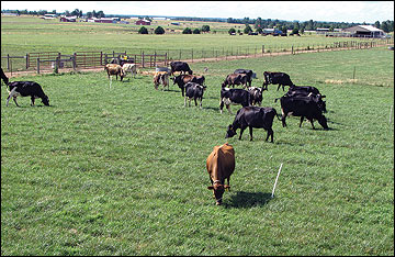 Figure 1
Fence and water distribution systems are keys to successful dairy grazing.
Grazing system design
Selecting and installing an appropriate fencing system for a grazing operation is an important step toward successful pasture-based dairy production. Three types of fence are likely to be used in a grazing cell: perimeter, permanent subdivision, and temporary or portable subdivision fencing. Electrified 12.5-gauge high-tensile wire is most satisfactory for perimeter fencing and permanent paddock fencing. The best options for portable fencing are polytape and polywire that consist of combinations of plastic and metal filaments.
Electrified high-tensile wire provides the lowest-cost option for permanent fence at about one-fourth the cost of net wire and half the cost of barbwire. The heavier galvanization on high-tensile wire than on common field fence also significantly increases life expectancy of the fence. Most fences wear out not from sun and rain but from animal pressure. Electrifying perimeter fences all but eliminates animal pressure on the fence. Perimeter fences should include as many wires as local regulation requires for legal fencing. Although dairy cattle are easily controlled with a single wire, liability is more limited when a legal fence has been installed. Electrified perimeter fencing also allows subdivision fences to be installed anywhere on the property. To provide maximum electrical flow to all parts of the farm, use 12.5-gauge wire or equivalent for all perimeter fencing.
When perimeter fencing has been installed, begin planning for pasture subdivision. Grazing cell designs can be broadly classified as either fixed or flexible. This designation refers to management options and the physical materials used in construction. Whether to use a fixed, flexible or combination system on a particular farm depends on several factors. Scale of the operation, need for management flexibility, and availability of labor and capital are the main considerations. Secondary factors include landscape conditions, seasonality of use, and integration into a mixed crop-livestock system.
Fixed vs. flexible systems
Fixed systems consist primarily of permanent fence and water installations. In this publication, a permanent fence is considered to be a single- or multiple-wire electrified high-tensile fence with braced corner assemblies. In a permanent watering facility, livestock return to the same physical location in every grazing period. Fixed systems can be advantageous for large grazing operations, operations with limited labor, and where pastures are considered permanent. They are disadvantageous for small operations due to high cost per acre and for operations where land is rotated from pasture to row crops or where mechanical harvest of forage is a routine practice due to small field size. In short, management flexibility is limited with a fixed system.
A flexible system consists of a framework of permanent or semipermanent fences with paddock subdivisions created within the framework using portable fences. In a flexible system, paddock size and number can be varied almost infinitely, providing tremendous management flexibility. Smaller farms, mixed crop and livestock operations, and high-value livestock operations such as dairies can use flexible systems most effectively. In an intensively managed dairy system, the use of portable fencing means that labor must be available to move fences daily. Using the right kind of fencing equipment, including fence reels and step-in posts, keeps labor requirements to a minimum (Figure 2). Water systems frequently use over-the-surface pipelines and small movable stock tanks.
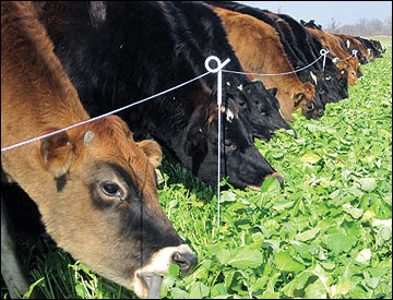 Figure 2
Polywire, fence reels and step-in posts reduce the labor requirements for portable fencing.
Cost per acre
The actual cost per acre for subdividing pastures depends not only on the number of subdivisions made but also on the size of the entire grazing unit. The larger the unit, the lower the cost per acre for both water development and subdivision fencing (Figure 3). The simple reason is that as size of an area increases, the ratio of perimeter to enclosed area decreases. Cost per acre for installing all permanent fence to create 10 paddocks for grazing units less than 80 acres can be substantial. Flexible systems can be used to reduce initial capital investment on small farms. In contrast, there is little cost change per acre as farms increase in size above 200 acres, making fixed systems more appropriate for larger grazing operations.
Two options for dividing a 140-acre pasture into multiple paddocks are shown in Figures 4 and 5, along with typical costs for fence and water system development. These examples assume that the power and pump system for water are already in place. Fixed fence and water systems typically require greater capital investment per acre to install. Fence material costs are higher because more total material is used and also because the heavier, longer-lasting materials used in fixed systems are usually more expensive. If a buried-pipeline water system is installed, trenching expense adds considerably to the development costs. Permanent watering sites are more likely to require use of concrete, gravel or other underlayment material, resulting in increased cost. As the number of permanent subdivisions increases, development costs will increase as more corners and gates are added to the system.
Flexible systems offer more management flexibility than do fixed systems. In most dairy operations, harvested winter feed is still required, and the mechanical harvesting of some paddocks is needed to keep pastures in high-quality condition. Whereas a fixed system places many constraints on mechanical harvesting and reseeding, flexible systems can be designed to facilitate easy equipment operation.
An important consideration in flexible systems design is spacing of the permanent fences and water lines and outlets. We recommend keeping the corridors created by permanent fencing less than 600 feet wide. With 50-foot post spacing on temporary fences, each fence line requires about 10 step-in posts. Ten step-in posts can easily be carried by hand. Longer fences require more posts, and the fencing process becomes more awkward. A fence of 600 feet or less can usually be taken down or put up in less than 10 minutes.
Another useful practice when setting up a flexible system is to space the line posts in the permanent fence in a way that allows for easy calculation of acreage. For example, if the corridor is 435 feet wide and line posts are spaced 50 feet apart, then every two line posts equals one acre. This design makes it easy to give instructions to children and hired help on where to place the next break fence.
Daily labor requirements are lower for operating a fixed system than a flexible system. Usually the day’s labor with a fixed system consists of opening a gate and letting the livestock into the next grazing paddock. Fence and water systems will need periodic maintenance, but labor input is generally lower in fixed systems. With a flexible system, temporary fence and water tanks need to be moved daily. Although the labor required for moving these components is usually not as much as would be required for hauling manure and chopping feed, the labor must be available to make regular and frequent moves.
In final comparison, flexible systems allow the manager much tighter control of forage supply, forage quality, pasture use, managing manure distribution, targeting specific landscape problems for animal management, and other variables. Control comes at the cost of increased daily labor and significantly more management decision making.
Any improvements in pasture facilities must be paid for by increasing livestock output or by eliminating or reducing some other cost. Although development costs are commonly expressed on a per acre basis, the final evaluation of economic feasibility must be based on additional animal product generated or on a lower production cost per unit. For example, the cost to subdivide 200 acres into ten 20-acre paddocks will be identical whether the 200-acre unit has a carrying capacity of 50 or 100 animal units (AU). Investment in pasture improvement will be paid off much more quickly on the pasture with 100 AU carrying capacity because it would have more saleable product over which to spread costs than would a 50 AU pasture. This consideration is why economic results from one region or type of operation should not be used to make decisions about economic feasibility of pasture improvement under other conditions. The bottom line is that the same level of management intensity is not appropriate for all regions or for all enterprises.
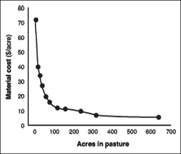 Figure 3
Material costs per acre for paddock subdivision decrease as pasture size increases.
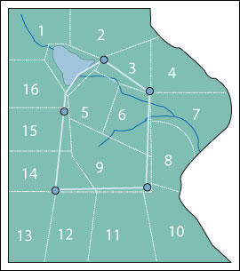 Subdivision fencing:
18,744 feet $4,850
= $34.64/acre
Water system:
Water lines and tanks $10,360
= $74.00/acre
Figure 4
An example of a fixed system grazing cell design on a 140-acre grazing unit with typical fence and water development costs based on single-wire electrified high-tensile fence and buried water lines.
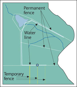 Permanent fence:
6,850 feet $1,770
= $12.64/acre
Water system:
Water lines and tanks $4,650
= $33.21/acre
Temporary fencing:
Three units $368
= $2.63/acre
Figure 5
The same 140-acre grazing unit as in Figure 4 configured in a flexible system grazing cell using permanent and temporary fencing and an over-the-surface water system.
Electric fence energizers
Modern electric fence energizers have the capacity to maintain effective voltage for animal control under much more adverse vegetative load conditions than earlier types. Low-impedance is the term most commonly used to describe the modern energizer. Low-impedance energizers are characterized by moderate voltage and very short pulse length. Joules are the most common means of comparing fence energizers. One joule is equal to an output of 1 watt per second. Energizers with longer output pulses will give a false impression of higher power than units with shorter pulse duration. Energizers must have a pulse length of less than 0.0003 seconds to be classified as low impedance. Comparison by joule output is only valid if pulse lengths are similar and if measured at comparable resistance levels. Output ratings for commercially available energizers range from 1 joule up to 60 or more joules.
Energizers are available as either plug-in units or solar-powered battery units (Figure 6). For most applications, plug-in energizers are preferred to solar units. Plug-in energizers are cheaper per unit of output power and generally require less maintenance than solar-powered units. Electricity cost for operating plug-in units is negligible: based on 8 cents per kilowatt hour (kwh), power cost will range from 5 cents a month for small units to about $1.50 a month for high-powered models. For remote areas where electric power is not available, running a single line of high-tensile wire to supply power is usually less expensive than buying and maintaining a solar-powered energizer.
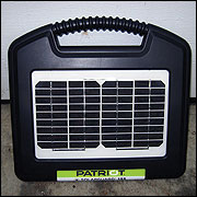
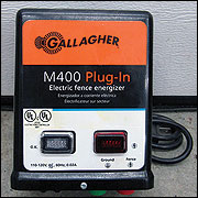 Figure 6
Electric fence energizers can be solar powered (left) or plug-in (above).
Sizing the energizer
The particular model of energizer to choose depends on the total distance of fence to be charged, anticipated vegetation load on the fence, and soil conditions. Manufacturer’s claims on this point can be confusing. If the energizer has a joule rating assigned to it, determining how many joules of power are needed for your situation should be simple. However, it usually is not so simple. One major fence company makes energizer recommendations based on the premise of half a mile of fence per joule of energizer capacity. Another manufacturer suggests up to 6 miles of fence per joule of energizer capacity. The first company is presenting a worst-case scenario, while the other is presenting a best-case scenario. Experience suggests that allowing one mile of fence per joule output will give satisfactory performance in most situations.
Type and construction of the fence will greatly affect the total mileage capacity of the energizer. Single-wire paddock subdivision fences for cattle are generally well up out of the vegetation and, if constructed from high-quality material, several miles of this type of fence can be electrified for every joule of energizer output. Multistrand perimeter fences may carry a heavy vegetation load on the lower wires, and an energizer will serve less total distance on a multistrand fence than it will on a single-wire fence.
If some paddocks are to be harvested as hay or silage, forage growth may cover the fence wires, which will increase the load on the energizer. In systems where forage harvesting is planned, install an energizer with higher joule capacity. Increased grounding is also beneficial for fence systems where a heavy forage load is anticipated.
Sandy or stony soils are poor electrical conductors and require both greater energizer capacity and more effective grounding systems than do clay or silt soils. Effective grounding will overcome many challenges to the fence system, but an undersized energizer on droughty soils is a constant problem.
Grounding systems
An electric fence energizer is only as effective as the grounding system installed with it (Figure 7). Grounding system requirements are determined by three factors: output capacity of the energizer, conductivity of the soil, and type of livestock or predator being controlled.
A minimum of 3 feet of ground rod per joule of energizer output capacity is required to realize the full potential of your energizer for controlling livestock. Galvanized or copper ground rods may be used. If using copper rods, make sure to also use a copper wire from the energizer ground terminal to the ground rod to prevent loss of effectiveness due to electrolysis occurring where two different metals are joined. Most energizers have stainless steel terminals, which can be safely joined to copper. If the energizer has galvanized terminals, then use only galvanized wire and ground rods. Ground rods are usually either 1/2 inch or 5/8 inch in diameter and 6 or 8 feet long. Galvanized pipe can be used effectively in place of manufactured ground rods. Wire should be clamped tightly to the ground rod either with a clamp made specifically for that use or with stainless steel pipe clamps.
Ground rods should be driven full length into the earth to reach moist soil year-round and should be a minimum of 10 feet apart. Placement on the north side of a shed under the drip line is ideal. In shallow, rocky soils, it may be impossible to put ground rods more than a few feet in the ground. In this case, it is crucial to find a location that is likely to remain moist year-round and lay the ground rods in trenches in this area. Again, the north side of a shed under the drip line works well. Locating ground rods in low, wet areas will enhance the effectiveness of the grounding system.
In shallow rocky or sandy soils, conductivity is quite poor. To enhance the effectiveness of electric fences in these environments, construct what is termed an earth-return fence system. In a conventional electric fence on a soil with good conductivity, generally all wires are energized, except in the predator-control situation where the earth-return system would be used. In an earth-return system, alternate wires are either electrically charged or noncharged and serve as part of the total grounding system. Just as all charged wires ultimately lead back to the fence terminal on the energizer, all ground wires lead back to the ground or earth terminal of the energizer. When an animal touches two alternate wires, the full impact of the total grounding system is brought to bear on the culprit animal. In this system it is important to have the ground wires either directly linked to the energizer earth terminal or to have each separate stretch of fence grounded with ground rods comparable to those serving the energizer.
The voltage required to maintain control of livestock varies with the type of livestock in the pasture. Dairy cattle usually have thinner hides and carry less winter hair coat than do beef cattle and thus are more easily controlled than beef cattle. Even though 3,000 volts is usually considered adequate for controlling dairy animals, maintaining a fence line voltage of at least 5,000 volts will help ensure animal control. Voltage delivered by modern energizers that are properly installed and where fences are maintained should easily surpass these minimum requirements.
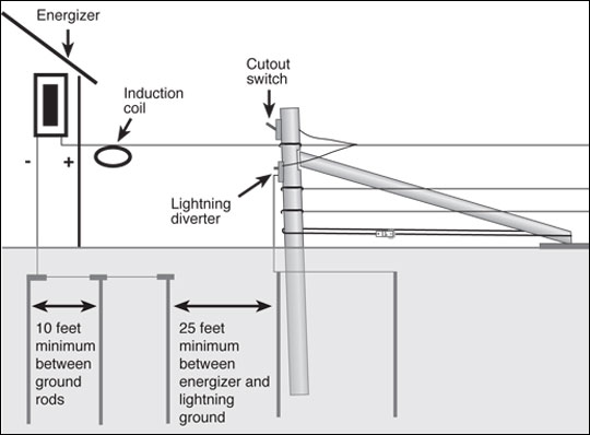 Figure 7
The effectiveness of an electric fence depends on an adequate grounding system.
Lightning protection
A common concern of all electric fence users is lightning strike and a blown up energizer. Mains units should be installed with lightning protection on both the incoming power side and the fence side. For incoming surge protection, a plug-in surge protector should be installed at the power outlet and the energizer plugged into the surge protector. This is the same type of protector as used on home computers and other valuable appliances and can be picked up at almost any appliance or variety store. Most rural electric systems experience daily variations in voltage flow that are as hazardous to electric fence energizers as lightning strikes, so a surge protector is good insurance for everyday use. Inadequate capacity in the electrical service entrance to many farm barns and shops is another cause of power surges. Dairy facilities that have been added on to in expansions are often deficient in electrical service capacity.
To provide lightning protection for a fence, several practices are advisable. First, place the energizer in a building in a low-lying area or a building protected by a lightning rod. Avoid placing it in a building on a hilltop with no lightning rods. Often, there is no choice where the energizer is to be installed, but when there is a choice, use common sense and stay away from lightning-prone areas. Burying underground cable rather than taking fence lines overhead to cross gates significantly reduces lightning risk.
Energizer ground stakes should be well away from the ground system of power poles or the service box. Never use the existing ground system of power poles or service boxes for the energizer ground. A short in the power line can feed into the fence system through the common ground and create a dangerously charged situation in the fence as well as damage the energizer. A lightning strike on a power line with a common ground with the energizer creates a situation where the energizer could be damaged through both the incoming line and the ground system. The ground system for the energizer should be placed at least 25 feet from the nearest power line ground rod.
An induction coil or lightning choke should be installed in the fence lead-out wire near the energizer. An induction coil is made by coiling six to eight loops of heavily insulated 12-gauge wire in an 8- to 10-inch diameter circle and taping the loops together. A lightning choke is made from a loose coil of high-tensile wire with 8 to 12 loops spaced about 2 inches apart on a mounting board. Either device acts as a lightning brake by forcing the high-voltage lightning surge into a circular flow and creating a resistance field by which the flow of lightning energy is reversed. The energy flow goes back up the fence and away from the energizer.
A lightning diverter should be installed where the lead-out wire attaches to the fence. A lightning diverter at this location serves the double purpose of diverting some of the initial energy surge to ground and providing a route of exit from the fence of the energy flow reversed by the induction coil. The most common form of lightning diverter is the porcelain twin tower. This device has two exterior terminals, and encased within the porcelain are leads that are set at a gap wide enough to prevent the energizer voltage flow from arcing across but close enough to allow a lightning voltage spike to jump easily across and pass to ground. The top terminal is attached to the top electrified wire and the lower terminal to a ground rod. The lightning diverter ground must be separate from the energizer ground. If a common ground rod is used, the lightning spike can pass through the common ground system and return to the energizer, potentially damaging the circuitry. Install several lightning diverters through the fence system at lightning-prone locations and where fences network together is relatively cheap insurance. Ideally, more total ground rod capacity should be installed under the lightning diverter system than under the energizer itself. Several other types of lightning diverters are available, but all work on the same principles as the twin tower.
Portable fence components
Wire
The most commonly used materials for portable fencing are polywire and polytape, with polywire being the more popular of the two. Both of these materials are combinations of plastic strands and metal filaments. Usually the plastic component is polyethylene and the metal is stainless steel. Other products are available that use polyester strands for structure and aluminum or tin-copper alloy for the conductors. The main feature of polyethylene products is that they are lightweight and require no tools for setup. Virtually no bracing is needed to hold the fence, and light-duty line posts may be used. The main limitation of polyethylene products is the distance that they can be energized before the internal resistance of the fine wire filaments used as conductors become restrictive.
Polywire has the appearance of heavy cord or plastic baler twine. It comes in several different grades, based on the number of filaments and the gauge of the conductor. Most polywire has either six or nine strands. The six-strand polywire can be effectively energized for distances up to half a mile. The nine-strand polywire not only has more wires but may also contain slightly larger wire filaments, increasing the practical length of fences to 3/4 to 1 mile. Either six- or nine-strand wires may contain two or three color filaments, which will improve the visibility and longevity of the material. More strands of plastic also serve to increase breaking strength and visibility of the product. Polywire may last up to 10 years with proper use. Each new generation of products has a longer useful life.
Reels
To use the polyethylene products effectively, a retrieval-dispersal system is a must. Many types of commercial reels are available, and some producers make their own. Features to look for in a commercial reel are a positive locking system, a good warranty, capacity to hold the amount of product typically used and, for some applications, high-speed gearing (Figure 8).
Reel capacities vary from as little as 300 feet of tape up to 1,320 feet. Polywire capacities may range from 660 feet to 2,640 feet or even greater. The reel capacity should be sized to the situation. If a 20-acre field that is 660 feet wide is to be strip grazed, there is no need to purchase a reel containing 2,000 feet of polywire. If stretches of 1,000 feet are necessary, using one reel with at least that much capacity will be more cost-effective than using two reels of lesser capacity. With a little forethought, you can easily avoid having an excessive amount of reserve capacity or coming up short. Size the equipment to the job to be done.
If fences are put up and taken down regularly or if numerous portable fences are used, a geared reel is helpful. Although basic reels work with a 1-to-1 retrieval ratio, a geared reel can retrieve polywire much faster. The usual ratio is 3-to-1. A geared reel will cost more than a 1-to-1 reel of comparable quality, but labor savings can quickly recover the initial cost.
Many other reel options are possible. Some producers use extension cord reels to hold polywire. These reels are much cheaper than designed fencing reels but may not be as convenient to use. Spools for welding wire and electrical wire can easily be converted to fence reels.
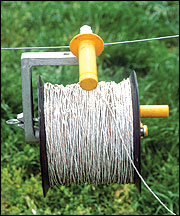 Figure 8
Portable electric fence reels can be used with wire or polytape.
Step-in posts
Plastic step-in posts and pigtail posts are the most common line posts used with polywire (Figure 9). Some people use metal rebar (reinforcing bar) or fiberglass rod posts with polywire, but each has its limitations. The weight of rebar and the need for insulators limit the efficiency of rebar posts. Fiberglass posts are useful as long as soil conditions allow the posts to be easily pushed into the ground by hand. When soil is hard, from either freezing or drought, posts must be hammered. To prevent the fiberglass from splintering, a driving cap must be used, although beating a post with a hammer does not lend itself to easy fencing.
Numerous models of step-in posts are available with a wide range of appearance and characteristics. One desirable characteristic is a step that is broad enough for a person’s foot to fit on and allow the post to be pushed into the ground. Many posts have only enough space for the edge of a shoe, which works well if the ground is moist but is inadequate if the ground is hard. The spike should have a large enough diameter to resist bending but should not be overly large. It is much harder to push a 3/8-inch spike into hard ground than a 3/16-inch spike. The post should be rigid enough to stay erect through windstorms and under slight fence pressure but flexible enough to bend under excessive pressure.
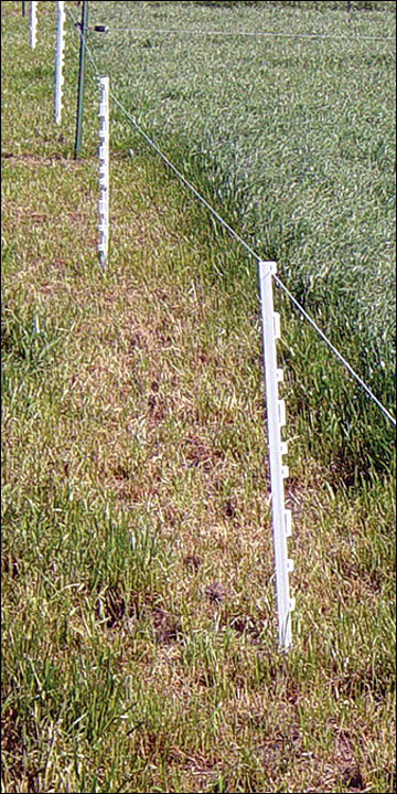 Figure 9
Step-in posts are used with polyethylene products in temporary fences.
Lanes and gates
Lanes are essential in a pasture-based dairy to move cows easily from pasture to parlor. Constructing raised lanes with adequate drainage capacity and using crushed rock, lime screenings or other stabilizing material reduces annual maintenance needs and keeps cows cleaner and healthier. Even small stones on the lane surface can increase herd lameness and culling, but topping lanes with waste lime and occasionally removing exposed rocks will minimize this problem. Lanes should not be too wide, as they are sacrifice areas that are not going to be productive and a wide lane encourages cows to loaf in the lane and to deposit manure there rather than on the paddock. If the lane is properly constructed, 16 to 24 feet is wide enough for animal traffic. If paddocks are expected to be mechanically harvested, plan to have a gate at the back of each paddock so that machinery traffic is not forced to use the livestock lane.
With permanent fence alleyways, a common question is where and how far apart to place gates. One of the advantages of single-wire fences is that they can be easily raised or lowered at almost any point. This flexibility eliminates the need for making permanent gateways in the lane system. With this approach, gates can be made anywhere along the lane just by raising the wire high enough for cows to walk under. The most common way of doing this is using 6- to 8-foot sections of 1-1/2- to 2-inch PVC pipe with a notch at the top to hold the wire (Figure 10).
If permanent gates are needed, pay special attention to the gate handles. There are two basic types of spring tension handles: extension and compression springs. Extension springs have the advantage that they have more leeway in fitting the opening (Figure 11). The primary disadvantage is that if cows push through the gate and stretch the spring, the handle is ruined. Compression springs have the advantage of surviving rushes through the gate. Gate wires may break and insulators may come off posts, but the handle usually remains intact. The main disadvantage is that there are only a few inches of give in the gate, so the gate must match the opening.
Gates should be constructed so that they are not hot when unhooked. Electric power should be transferred across the space occupied by the gate via overhead wire or insulated underground wire run through plastic pipe or conduit.
Polytape or larger diameter polycord are materials that can be used to make gates because of their high visibility. Cable makes good gates because it usually does not kink if thrown back out of the way. High-tensile steel wire makes poor gates because it is hard to keep tight, particularly with compression handles, and it is also prone to kinking if not handled carefully. Aluminum wire can be used for gates because it has excellent conductivity and maintains good visibility. However, it is also prone to kinking if not handled carefully.
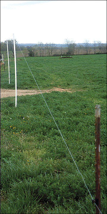 Figure 10
Single-wire fence raised to allow cows entry into a paddock.
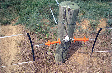 Figure 11
An insulated gate handle with an extension spring provides leeway in fitting the opening.
Water distribution system components
Water source
A livestock water system includes both a water source and a water distribution system. Water sources may include ponds, wells, springs, creeks or public water systems. Because rural water costs are rising in many areas, dairies using rural water districts to water livestock may find that developing surface impoundments results in significant savings.
Keeping animals from entering the water source, such as a pond or spring, will maintain higher water quality and result in better livestock production. In many states, existing or pending legislation will exclude grazing animals from using certain natural water sources. Before developing a water source for your grazing system, check local regulations and attitudes to ensure that your source remains viable for many years to come.
Water distribution
The water distribution system must be designed to supply water under peak demand. Traditionally the solution to this problem has been to use a large reservoir with limited recharge capacity. This approach is based on herd behavior when it comes to water access. When animals travel a long distance to water, many attempt to drink at the same time and the tendency is for each animal to drink for an extended period. Adequate tank space must be present for a large number of cows to drink at one time.
During midsummer in the Midwest, lactating cows will typically travel to water three to five times a day if they do not need to travel more than 600 to 800 feet. At greater distances, they will travel to water less frequently but will stay longer and drink for a longer period. On each trip to water, a cow will typically drink for one to four minutes at a rate of 1 to 2 gallons per minute. By knowing these values for cows or other types of livestock, you can calculate the water demand rate for any herd. If 10 cows can get to the tank to drink at one time and each cow drinks 2 gallons per minute, the tank must either have a substantial reservoir or the control valve must recharge the tank at a rate of 20 gallons per minute. When water is placed closer to the animals, the social behavior of drinking is broken up and water access becomes more of an individual behavior. If larger pipe sizes and high flow-rate valves are used, much smaller water reservoirs can accommodate fairly large herds.
In any system, pipe capacity must be adequate to supply all watering points that are in use in the system at the same time. Table 1 illustrates the effect of increasing pipe size and pressure head in gravity-flow situations. Each 2.3-foot rise or drop in elevation will increase or decrease water pressure by 1 pound per square inch (psi). If a high-recharge system with small drinking reservoirs is to be used, the pipe and pressure in the system must be adequate to keep the reservoir filled. Failure to keep the reservoir filled often results in animal damage to the drinking facilities. Trenching is often the highest cost component when installing a water distribution system. Always install a pipe size larger than you anticipate needing to avoid having to trench in a larger line later.
Table 1
Effect of pipe size and pressure head on water flow rate in a gravity-flow system.
| Pressure head | Pipe diameter (inches) | ||
|---|---|---|---|
| 1.0 | 1.5 | 2.0 | |
| Gallons per hour | |||
| 6 foot | 285 | 840 | 1,790 |
| 12 foot | 405 | 1,185 | 3,535 |
Water systems for large dairy operations consist almost completely of buried waterlines and permanently installed stock tanks. Most water distribution systems for small to medium-sized dairies consist of some buried main waterlines and a network of over-the-surface lines and movable tanks. In large-scale permanent grazing systems, underground piping is more appropriate for distributing water to individual paddocks because the space required for the herd to drink makes small, movable tanks much less practical. Size and type of pipe to use depends on specific situations and local availability. The required size of pipe depends on the distance that water is to be transferred, pump pressure, elevation changes, and number and class of livestock to be watered. As distance increases, larger diameter pipes are required because the longer the pipe, the greater the loss of pressure due to friction. Gravity-feed systems require a larger diameter pipe than pressure systems because they generally operate at substantially lower pressures. There is a practical limit to the number of head that can be watered effectively with a low-pressure, gravity-feed distribution system.
Pipe materials
There are two primary materials used for stock water pipeline systems in the Midwest: polyvinyl chloride (PVC) and polyethylene (PE). Each material has advantages and disadvantages in specific applications. Both types of pipe come in a variety of sizes and pressure ratings.
PE pipe is the rolled, typically black, plastic pipe. It comes in various pressure and quality grades. Most livestock water systems use either 100 or 160 pounds per square inch (psi) rated pipe. Low-pressure gravity systems can use the 100 psi pipe, whereas pressurized systems should use the 160 psi pipe. A good PE pipe is usually more expensive than PVC pipe. The main advantage of using PE pipe in a water system is that it requires fewer joints than a jointed PVC system and therefore provides less opportunity for leaks to develop. PE pipe has more flexibility as soil conditions change through droughts, floods and winter conditions. There are two types of PE pipe: low-density PE (LDPE) and high-density PE (HDPE). The HDPE has more expansion and contraction capability than does LDPE and is the preferred material for water distribution in grazing systems.
Disadvantages of PE in relation to PVC include higher cost, reduced flow and a tendency for rodents to eat PE pipes. A PE pipe is restricted to less than its specified dimension because of the spear-type fitting used to join pipe or make tees. These fittings result in a lower flow rate through PE pipe than through PVC pipe of the same nominal size. Connections with PVC pipe are based on a constant outside diameter, so lighter-grade PVC pipe provides greater flow than its nominal size.
Most PVC pipe is purchased in 20-foot sections and is joined either by glued joints or by slip-in gasket joints. Glued joints require a little more labor for installation but rarely leak if properly done. Gasketed joints provide a little more flexibility as soil conditions change but may be prone to leakage in some clay soils, which expand and contract as moisture content changes.
In stony soils, PVC pipe is more likely to develop leaks due to pipe breakage if the pipe is not carefully placed in the trench and if backfilling places rock directly on the pipe. In stony conditions a bed of sand is sometimes added to the bottom of the trench before the pipe is laid, and a covering layer of sand is also added. Because PVC pipe is rigid, it is much more prone to breakage from freezing or mechanical damage than is PE pipe.
Tanks
A wide variety of options are available in stock water tanks. These options range from open tanks constructed of steel, plastic or concrete to insulated freeze-proof tanks that are generally considered to be serviceable during all seasons. Some types are portable, whereas others should be installed in one location permanently.
Open tanks are a logical choice in many situations. During the grazing season when freezing is not a concern, they offer an economical option for permanent watering stations. Tanks should be sized and located so as to allow cows plenty of room to drink without crowding.
Concrete tanks are a favorite of many producers and in many situations. They are extremely durable and relatively easy to install during the construction process. Properly installed, they are highly resistant to freezing and provide an economical year-round water source. Concrete tanks should be trouble-free for many years.
A new innovation in recent years is the use of large-implement or heavy-equipment tires for livestock water tanks (Figure 12). Tires are durable and resistant to freeze damage. Installation is fairly easy as the tire can be placed over the pipe riser and sealed with either concrete or bentonite poured up to the bottom bead of the tire. Tires are virtually freeze-proof when animals drink from them regularly. If desired, they can be plumbed with overflow pipes and kept open in winter by allowing a continuous trickle of water to flow through them. Concrete-bottom tanks may require sealing with mastic or silicon around the pipe and tire-concrete joint to prevent leaks.
Plastic ball–type water tanks are preferred in some situations by some producers. These tanks are designed to withstand freezing temperatures and are generally carefree in winter as long as animals use them regularly. A potential drawback to ball-type tanks is that they provide limited access space to animals. If installing this type of tank for dairy animals, pay special attention to the number and size of tanks needed to provide adequate drinking space.
Proper installation of any permanent tank will include incorporation of a stable non-eroding surface in the area of heavy livestock traffic near the tank. A good pad will reduce ground wear and prevent mud formation around the tank. One option for ground stabilization is to install a concrete pad around the tank. Another option would be a gravel pad. Gravel may not be as stable as concrete but is less expensive. A gravel pad’s performance can be improved by using geotextile stabilizing materials during construction.
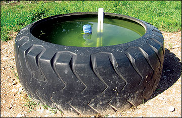 Figure 12
Large tires make good livestock watering tanks.
Float valves
Float valves are an important component in the water system for two main reasons. First, they control the use and waste of water. Continuously flowing water systems are wasteful of water and create muddy messes if the overflow is not properly installed and maintained. Second, they determine how much water is being delivered to the animals. Water systems are sometimes installed with proper attention paid to sizing the pump and pipeline, but then water flow is restricted by use of the cheapest valve available.
Float valves may be of either the full-flow or restricted-flow type. A full-flow valve will allow nearly the total pipe capacity to flow through when it is opened. This type of valve is especially suited for the small-reservoir/high-recharge water systems. Restricted-flow valves may reduce the pipe flow by as much as 80 percent. They should be used only in large-reservoir/low-recharge systems.
Some full-flow valves are unable to handle pond water containing algae or impurities. Valves with small openings or fine-mesh filter screens are prone to plugging. Removal of the filter screen will allow some of these valves to perform satisfactorily. On other valves, removing the screen may actually aggravate the problem. The best method for selecting a valve that will work in your system is to consult other graziers managing similar livestock in your environment.
Portable water systems
Temporary water systems using movable tanks and plastic pipe laid over the soil surface work well in smaller operations for seasonal use. Such a system allows flexibility in daily forage allocation and keeps stock away from areas used for watering and loafing in preceding grazing periods. Portable systems are practical for dairy herds of up to about 100 cows.
Key components of a portable watering system are pipe, couplers and tees, quick attach valves (Figure 13) and movable tanks (Figure 14). Pipe should be UV stabilized to prevent rapid degradation in direct sunlight. Most pipe sold at plumbing stores is designed for underground installation and is not highly UV stabilized. Rolled high-density polyethylene (HDPE) is normally used aboveground because it has the ability to expand and contract without splitting when water freezes and it does not become brittle in sunlight. The more commonly available low-density polyethylene (LDPE) pipe sold at many farm and home stores is not suitable for long-term aboveground use. Pipe size needs to be matched to the animals’ drinking demand, especially in gravity-feed and siphon systems, where 11/4-inch pipe should generally be the smallest pipe used.
Many of these systems use twist-on or snap-on couplers that require no tools and no hose clamps for installation. This is certainly an advantage but does add to the cost of the system. Main lines that are rarely moved can be installed using less-expensive conventional fittings while easy-to-use snap-on connectors are used on lines that are frequently moved or tapped into (Figure 14). Snap-on valves are ball valves that work on the same principle as hydraulic couplings and can make water instantly available wherever a tank is placed when a new paddock is set up.
Many producers are surprised at how small a water tank can be used with these systems. There are two reasons tank size does not have to be excessive. First is that when stock are confined on smaller paddocks than are used for continuous grazing, watering ceases to be a major social function in which the entire herd takes part. When it is a quarter to a half mile to water, the entire herd travels together. When water is always within a few hundred feet, the animals behave more as individuals or as family groups when accessing water. The second reason for a small drinking reservoir is that new-generation flow valves allow full-pipe flow as soon as a water level drops to activate the valve. The trickle-style refilling that many older valves provide required a large drinking reservoir. Nearly instantaneous refilling allows a much smaller reservoir to be used.
Some producers have expressed concern about the temperature of water in aboveground systems when black pipe is used. This has not been a problem in our experience. The volume of water contained in the pipe where heating is likely to occur is typically quite small relative to the water reservoir from which stock are drinking. As the pipe lies out for a grazing season, it settles down into the soil, and the water is cooled by earth contact. If the pipe is laid along a fence line, often enough shading is present to prevent excessive heating.
If stock are allowed access to water at all times, the maximum distance they should be forced to travel is a quarter mile. As stock walk greater distances to water, more and more energy that could be used for milk production is diverted to maintenance, and less manure is returned to the paddock. Availability of water in every paddock is ideal and should be the long-range objective of all graziers.
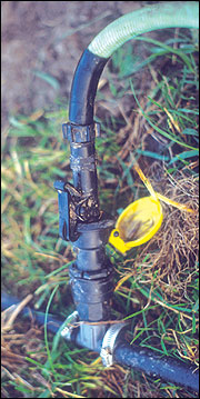 Figure 13
Quick-attach valve for a portable water system.
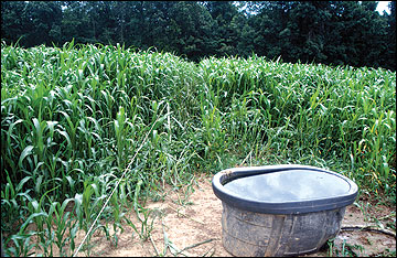 Figure 14
Plastic portable waterer with hose on ground to avoid damage.
Water access by lane
If short-term capital or labor limitations prevent installation of water in every paddock, it may be necessary to bring stock to the watering site. Access to water is generally by way of a lane that connects all the paddocks to the water source, or the paddocks radiate from a common water source as in a wagon-wheel design. If a lane is used, it should follow a level contour as much as feasible. The two main reasons for this are to prevent the development of gullies where animal traffic is concentrated, and to take advantage of animal energetics. It takes more maintenance energy for livestock to climb hills than to walk a level track to reach water. Lanes may be situated on ridge tops, along valley floors, or along any contour line that is convenient. Broad-base terraces on converted cropland make a nice lane.
Where the lane is also needed for moving cows to and from the milking facility, lane design should be given a high priority. Paddock gates into lanes or other central animal traffic points should be placed in the corner of the paddock toward which livestock would naturally gravitate. Setting up paddocks and lanes to fit normal animal travel movement will reduce fence maintenance requirements and enhance system performance. Avoid placing gates at sites where gullies are likely to develop. Gateways into paddocks should be the same width as the lane so as to eliminate animal travel in the alleyway beyond the open paddock.