Hydraulic collection and transport is a preferred method of handling livestock manure for many producers. Hydraulic methods tend to reduce labor and equipment requirements and take advantage of gravity in the movement of manure. However, most manure, as excreted by the animal, is too thick (solids content is too high) to move hydraulically. Therefore, a typical practice is to use recycled effluent from the manure lagoon to dilute manure so that it can be collected and transported hydraulically to the lagoon. Figure 1 is a schematic diagram of a typical recycle system. Pit recharge systems for swine and flush systems for dairies are typical examples of the use of recycled lagoon water for dilution and hydraulic transport of manure (Figure 2).
A common problem in these manure-handling systems using recycled lagoon water is the buildup of crystals in various components of the system. Pump impellers, piping, flush tanks, flush gutters and drain lines are all susceptible to crystal buildup. Crystal formations can cause leaking seals and degrade performance of pumps. Accumulations in a pipe reduce flow area and can eventually stop flow in the pipe (Figure 3). The severity of the crystal problem depends on many factors, including chemical characteristics of the lagoon effluent, selection and design of system components, and effluent flow rates in the recycle system.
Crystal accumulation can be a major hindrance in the use of recycled lagoon effluent to collect and transport manure hydraulically. To date no feasible means of preventing crystal buildup has been developed. However, by using certain design and maintenance procedures a producer can usually use recycled lagoon effluent in an acceptable manner.
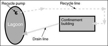 Figure 1
A typical recycle system for manure collection and removal.
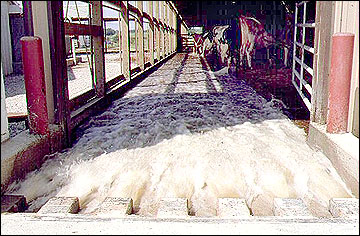 Figure 2
This dairy flush system uses effluent recycled from an anaerobic lagoon.
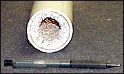 Figure 3
Crystals have reduced the flow area in this 2-inch PVC pipe by about 75 percent.
Crystal formation
The troublesome crystals that form in pipes and other components of systems using recycled anaerobic lagoon effluent have been identified as a compound called magnesium ammonium phosphate (commonly referred to as "struvite"). This compound has been known and experienced for many years in the municipal wastewater systems. Crystallization has also become prevalent in the agricultural sector with the development of manure recycle flush and handling systems. Many factors contribute to the formation of the magnesium ammonium phosphate crystal "struvite" (MgNH4PO4 - 6H2O), including the following:
- The concentration of magnesium, ammonium and phosphate ions in the recycled lagoon effluent. Nearly all anaerobic manure lagoons contain these ions in sufficient concentration to support crystal formation to some degree. Generally the higher the concentration of these ions, the more likely it is that crystal formation will occur.
- The pH of the lagoon effluent. Most anaerobic manure lagoons exhibit pH in the range of 6.5 to 8.0. Crystal formation is common in this pH range.
- Materials used in the recycle system. Experience has shown that crystals are much more likely to occur when metallic structural or piping components (black iron, galvanized iron, steel, cast iron, brass, bronze, copper) are used in the system. Plastic, rubber, or other synthetic materials do not become encrusted as readily.
- Contact time and volume of effluent handled in the recycle system. A recycle system designed for continuous pumping at the rate of 50 gallons per minute will circulate more than 26 million gallons in the course of one year. Such intense use affords ample opportunity for crystal formation.
- Physical configuration of the recycle system. Pipe fitting components such as elbows, tees, valves and reducers, whether metallic or plastic, tend to have edges or protrusions, which can trap grit or other particulate matter. Such trapped material provides a base for crystal formation and growth. Crystal growth is commonly expected to be more prevalent at these points in the system. Encrustation is less severe but also occurs in smooth portions of plastic pipe. Typically, crystals begin to form in the bottom of the pipe and then proceed around the circumference and longitudinally along the length of the pipe.
In any given case, there may be other factors contributing to crystal formation. The complex interaction of the many possible factors makes the severity of crystal buildup difficult to predict. When anaerobic lagoon effluent is recycled in a manure management system, the possibility of crystal problems should be expected, and measures should be taken to minimize potential problems.
Solutions
Although no feasible means of preventing crystal buildup has been identified or developed, experience has shown that certain considerations can minimize the problem to an acceptable level. These considerations can be categorized as
- Design considerations
- Operation and maintenance considerations.
Design considerations
A number of design considerations have been shown to reduce problems of crystal buildup in lagoon recycle systems.
- Proper lagoon design. The lagoon should be properly designed and sized for the number of animals contributing manure to the system. Undersized lagoons develop higher concentrations of magnesium, ammonium and phosphate ions, and thus are associated with more severe crystal problems.
- Avoid the use of metallic components in the system wherever possible. Use pumps with plastic volutes and impellers, plastic pipe, and plastic valves and fittings when designing the pumping system.
- Minimize the number of fittings in the system to the extent possible. Elbows, valves, tees, short 90- degree bends and other fittings tend to accumulate crystals more quickly than smooth pipe. Use flexible plastic pipe to the extent possible to eliminate elbows. Long-radius 90-degree elbows are preferable to short bends.
- Use larger pipe sizes than might be indicated by traditional hydraulic design. A larger pipe size provides greater flow area or cross section per unit of wetted perimeter or circumference where crystals can occur. For example, a 4-inch pipe has twice the flow area per inch of circumference as does a 2-inch pipe. Further, larger pipe sizes can accommodate some crystal growth without degrading flow characteristics significantly. Consider that one-quarter inch of crystal growth around the periphery of a 4-inch pipe reduces the cross sectional flow area by about 23 percent, while the same one-quarter inch buildup around the periphery of a 2-inch pipe reduces the flow area by about 45 percent. Current recommendations suggest sizing the recycle pipe so that flow velocities are 2.0 to 2.5 feet per second. Do not use pipe smaller than 2 inches in diameter.
Operation and maintenance considerations
Operation and maintenance considerations include procedures to remove crystals on a regular, periodic basis after they have formed in the system. These procedures should be implemented on a schedule such that crystals are removed before growth becomes so extensive that pump performance or flow rate is impaired. The most widely used procedure in this category is acid washing, or the use of a commercial de-scaling product to dissolve crystals from the system on a periodic schedule. Magnesium ammonium phosphate crystals readily dissolve in a low-pH environment, and this characteristic can be used to remove crystals in a recycle system.
Acid washing systems. Acid washing involves the introduction of a diluted acid into the entire recycle system to dissolve crystals. Simply filling the pipes and other components of the recycle system with an acid solution and letting it "sit" for a period of time to dissolve the crystals is not as effective as circulating an acid solution through the system for a period of time. Hence, an acid washing system should include the necessary piping, valves, pumps and other components so that the acid solution can be circulated in the recycle system as needed to dissolve the crystals. Figure 4 shows how an acid circulation system might be implemented.
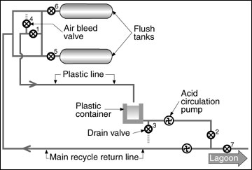 Figure 4
Schematic of an acid recirculation system.
With reference to Figure 4, the system is operated as follows:
- Under normal recycling operations, valves 1, 2, 3 and 4 are closed, and valves 5, 6 and 7 are open. This configuration allows lagoon effluent to be pumped to the flush tanks or other holding areas.
- When preparing to circulate acid, first allow as much lagoon effluent as possible to drain back to the lagoon from the pipes. This will minimize unwanted dilution of the acid solution.
- Close valves 5, 6 and 7 to isolate the lagoon and flush tanks or holding areas from the system.
- Open valves 1 and 2 to form the closed-loop circulation system. Use the acid circulation pump or main recycle pump to circulate the acid solution through the system.
Valve 4 should be located at a "high" point in the system and can be used to release or purge air from the system when preparing to circulate the acid solution. Excess lagoon effluent can be purged from the system by diverting the acid return line to the lagoon until acid starts arriving back to the acid storage reservoir (plastic container in Figure 4).
The acid return line should be at least half the diameter of the main recycle line, and the acid storage reservoir should be, at minimum, large enough to hold the volume of acid solution required to fill the piping in the system. Table 1 shows the volume per foot of length contained in pipes of various sizes.
Table 1
Volume of a pipe per foot of length.
- Pipe size
2 inches
Volume contained
0.16 gallons per foot length - Pipe size
3 inches
Volume contained
0.17 gallons per foot length - Pipe size
4 inches
Volume contained
0.65 gallons per foot length - Pipe size
6 inches
Volume contained
1.47 gallons per foot length
Example
A system with 400 feet of 4-inch main recycle line, and 400 feet of 2-inch acid return line would require an acid reservoir size of at least 400 x 0.65 + 400 x 0.16 = 324 gallons. Hence, an acid reservoir with a volume of 350 to 400 gallons should be selected.
A separate acid circulation pump may not be necessary if the main recycle pump can be used to circulate the acid solution. However, if the main recycle pump is a submersible pump in the lagoon, or in a wet well, it may be more convenient to provide a separate acid circulation pump, which stays plumbed into the system. The submersible pump is then acid washed separately, usually by placing the pump in a container of acid solution.
Almost any acid of sufficient strength will dissolve the magnesium ammonium phosphate crystals. Glacial acetic acid mixed 1:50 with water has been used successfully. Muriatic acid (generally available at concrete plants) diluted at the rate of 400 gallons of water per 55-gallon drum of acid has also been used effectively. Observe appropriate safety precautions when working with acid. It can cause injury! The acid reservoir should be placed within a secondary containment facility to contain any spills or leaks. All components of the system containing acid should be labeled as a potential hazard.
Acid-wash the system on a regular schedule as needed before excessive crystal buildup occurs. Crystals are much easier to dissolve and remove before flow in the system is reduced significantly. If crystals are allowed to completely block flow, acid washing will not work, and the system will have to be replaced. Acid used to dissolve and remove crystals will eventually become neutralized (pH elevated) until it is no longer effective in dissolving crystals. When this condition occurs, the acid may be drained to the lagoon, and a "fresh" volume of acid is used for the next washing. Acid washing systems can be implemented in most recycle systems and are particularly applicable to complex systems involving multiple flow circuits or branches or long flow paths that cannot be easily cleaned by other means.
Hydraulic crystal removal. Some success has been experienced using water under high pressure to break up or erode crystal formations from the components of recycle systems. With this approach, a high-pressure washer with pressure and flow characteristics in the range of 2,000 to 2,500 psi and 4 to 5 gallons per minute is used with a special "sewer nozzle" to clean crystals from pipes (Figure 5).
 Figure 5
This sewer nozzle is made of stainless steel for long-term durability.
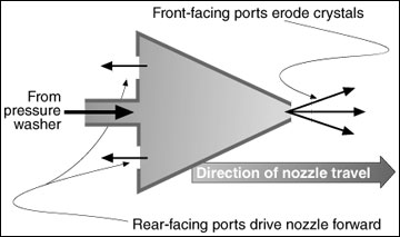
Figure 6
Schematic drawing of a sewer nozzle used to clean crystals from a recycle pipe.
The sewer nozzle has a forward-facing port that discharges water at a high velocity to erode and break up crystal formations. The nozzle also has rear-facing ports that drive the nozzle forward along the length of pipe as it is cleaned. Figure 6 is a conceptual sketch of this type of nozzle.
Since the sewer nozzle is fed by a high-pressure hose (typically 1.4 inch in diameter), this approach is limited to systems, which will allow movement of the nozzle and hose within the pipe. Smooth, continuous pipe and long-radius elbows must be used in the piping system so the sewer nozzle and hose can be inserted and travel along the length of the pipe. With this approach, cleaning should begin at the discharge end of the recycle system, and the recycle pump should be operated during cleaning to flush the eroded crystals from the pipe.
Summary
The formation of magnesium ammonium phosphate struvite crystals in recycle systems using anaerobic lagoon effluent is a common and problematic occurrence. To date, no feasible means of preventing the development of these crystals has been identified. However, with proper design and management of the system, including the lagoon, the crystal problem can be controlled in an acceptable manner. Acid washing at regular intervals is the most commonly used method of controlling crystals in recycle systems.
For further information
- Booram, C. V., R. Smith, and T. Hazen. 1975. Crystalline Phosphate Precipitation from Anaerobic Animal Waste Treatment Lagoon Liquors. Transactions of the American Society of Agricultural Engineers. American Society of Agricultural Engineers, St. Joseph, Mich.